Transformer

A technology of transformers and shielding parts, which is applied in the field of transformers and can solve problems such as reducing stray losses

Inactive Publication Date: 2019-03-26
济南西门子变压器有限公司
View PDF17 Cites 0 Cited by
  • Summary
  • Abstract
  • Description
  • Claims
  • Application Information

AI Technical Summary

Problems solved by technology

The existing magnetic shielding device has little influence on the leakage flux when the size of the transformer is small, and cannot reduce the stray loss well

Method used


Image

  • Transformer
  • Transformer
  • Transformer

Examples


Embodiment Construction

[0030] In order to have a clearer understanding of the technical features, purposes and effects of the invention, the specific embodiments of the present invention are now described with reference to the accompanying drawings, in which the same reference numerals represent components with the same or similar structures but the same functions.

[0031] In this article, "schematic" means "serving as an example, example or illustration", and any illustration or implementation described as "schematic" should not be interpreted as a more preferred or more advantageous Technical solutions.

[0032] In order to make the drawing concise, each drawing only schematically shows the parts related to the present invention, and they do not represent the actual structure of the product. In addition, in order to make the drawings concise and easy to understand, in some drawings, only one of the components having the same structure or function is schematically shown, or only one of them is mar...


PUM


Abstract

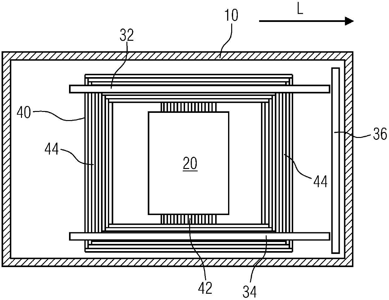
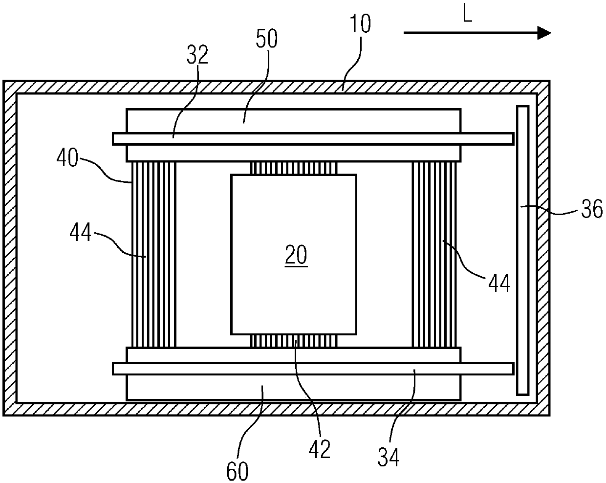
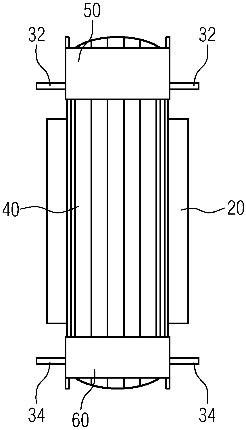
A transformer includes an oil tank (10), an iron core (40), a set of windings (20), an upper shield (32), a lower shield (34) and a side shield (36). The iron core includes a main core column (42) andtwo side columns (44) along the length direction (L). The windings sleeve the main core column. The upper shield is arranged in the oil tank and on one axial side of the windings, and the length of the upper shield along the length direction covers the iron core. The lower shield is arranged in the oil tank and on the other axial side of the windings, and the length of the lower shield along thelength direction covers the iron core. The side shield is arranged in the oil tank and on one side of the winding along the length direction, and the length of the side shield in a direction parallelto the axial direction of the windings covers the windings, the upper shield and the lower shield. A leakage flux path is formed in the length direction of the transformer provided by the invention toguide leakage flux, so that stray loss caused by leakage flux is reduced.

Description

technical field [0001] The invention relates to a transformer, especially a transformer with a magnetic shielding device. Background technique [0002] During the operation of the transformer, leakage flux will be generated around the winding, and stray loss will be generated when the leakage flux passes through the tank wall. In order to solve this problem, a magnetic shielding device is usually designed in the power transformer to allow the leakage flux to preferentially pass through the magnetic shielding device with better magnetic permeability, thereby reducing the stray loss caused by the leakage flux on the tank wall. The existing magnetic shielding device has little influence on the leakage flux when the size of the transformer is small, and cannot reduce the stray loss well. Contents of the invention [0003] The purpose of the present invention is to provide a transformer that can effectively guide leakage flux and reduce stray loss when the size of the transfor...

Claims


Application Information

Patent Timeline
Patent Type & Authority Applications(China)
IPC IPC(8): H01F27/36
CPCH01F27/36
Inventor 付大金唐康毅周剑杨智强王桂平
Owner 济南西门子变压器有限公司
Why Eureka
Try Eureka