Extension arm for a free arm parasol, pivotably arranged on a carrier

a technology of free arm parasols and extension arms, which is applied in the direction of machine supports, umbrellas, other domestic objects, etc., can solve the problem of limited number of pivoted angles of guide rods on the extension arms

Active Publication Date: 2008-07-15
GLATZ AG
View PDF11 Cites 72 Cited by
  • Summary
  • Abstract
  • Description
  • Claims
  • Application Information

AI Technical Summary

Benefits of technology

[0005]Owing to the fact that a first coupling part, which is connected fixedly to the extension arm, interacts with a second coupling part, which is formed on the sleeve and is effective in the axial direction, the guide rod having a supporting element which interacts with a counterpart arranged on the extension arm, the second coupling part can be displaced in the axial direction by means of the guide rod and, in the process, can initiate the coupling and decoupling without additional members having to be actuated. By means of the guide rod, in the decoupled state the sleeve can be pivoted freely about the extension arm and, in the coupled state, the extension arm can be pivoted by means of the same guide rod.
[0007]A particularly simple configuration of the guide rod has a fork-like supporting element and is coupled with the latter to the second coupling part via two bearing bolts.
[0009]In order to avoid injuries, it is expedient if one of the coupling parts has a sleeve part surrounding the coupling region and / or spring region, so that an unintentional intervention of an operator in the coupling region and / or spring region is prevented.
[0011]Various possibilities likewise emerge for the design of the supporting element. In alternative embodiments, the supporting element can be arranged on an upper arm of the guide rod and can have a stop lug or can be designed as a one- or two-sided eccentric. The stop lug, or the one- or two-sided eccentric, is connected in a sliding manner to the counterpart on the extension arm, the second coupling part being preloaded toward the first coupling part by means of a preloading spring. The preloading spring is preferably arranged in the interior of the sleeve-like, second coupling part and is supported at one end on the coupling part and at the other end on the extension arm. The arrangement of the preloading spring in the sleeve-like, second coupling part prevents accidents.
[0013]In another embodiment, the guide rod has a retaining device on its lower section, by means of which the guide rod can be retained on the carrier. The retaining element can be configured as a resilient retaining clip. In this case, it is advantageous if the retaining clip is connected to the guide rod in an articulated manner in order to be able to adapt to changes in position during the displacement along the carrier. It is particularly advantageous if the retaining element, is configured as a retaining lug which engages in a longitudinal slot arranged on the pole. In this case, it is advantageous if the retaining lug comprises two lug parts which are arranged at a distance from each other and engage on side parts of the longitudinal slots in a retaining manner. To this end, it is advantageous if the lug parts are resilient. It is particularly advantageous if the lug parts are secured against becoming unlatched from the longitudinal slot by means of a blocking slider. In this case, the arrangement can nevertheless be undertaken in such a manner that a movement of the supporting element along the carrier is possible even when the retaining clip is latched.

Problems solved by technology

It is disadvantageous here that, firstly, the possible number of pivoted angles of the guide rod on the extension arm is limited.
Secondly, during the actuation of the hand lever to unlatch the latching bolt by pulling radially on the handle and to pivot the guide rod, two maneuvers are always required.

Method used


Image

  • Extension arm for a free arm parasol, pivotably arranged on a carrier
  • Extension arm for a free arm parasol, pivotably arranged on a carrier
  • Extension arm for a free arm parasol, pivotably arranged on a carrier

Examples


Embodiment Construction

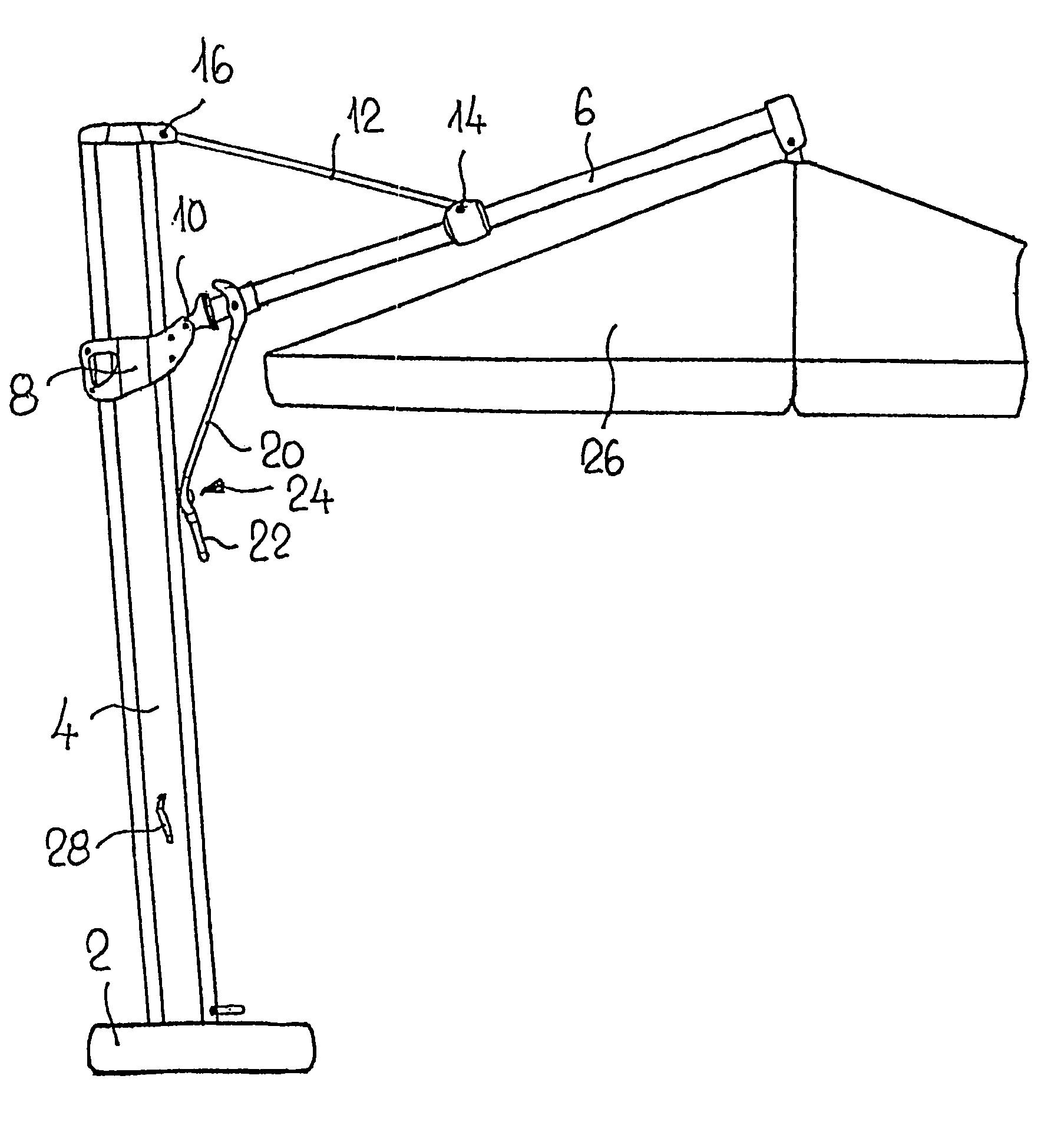
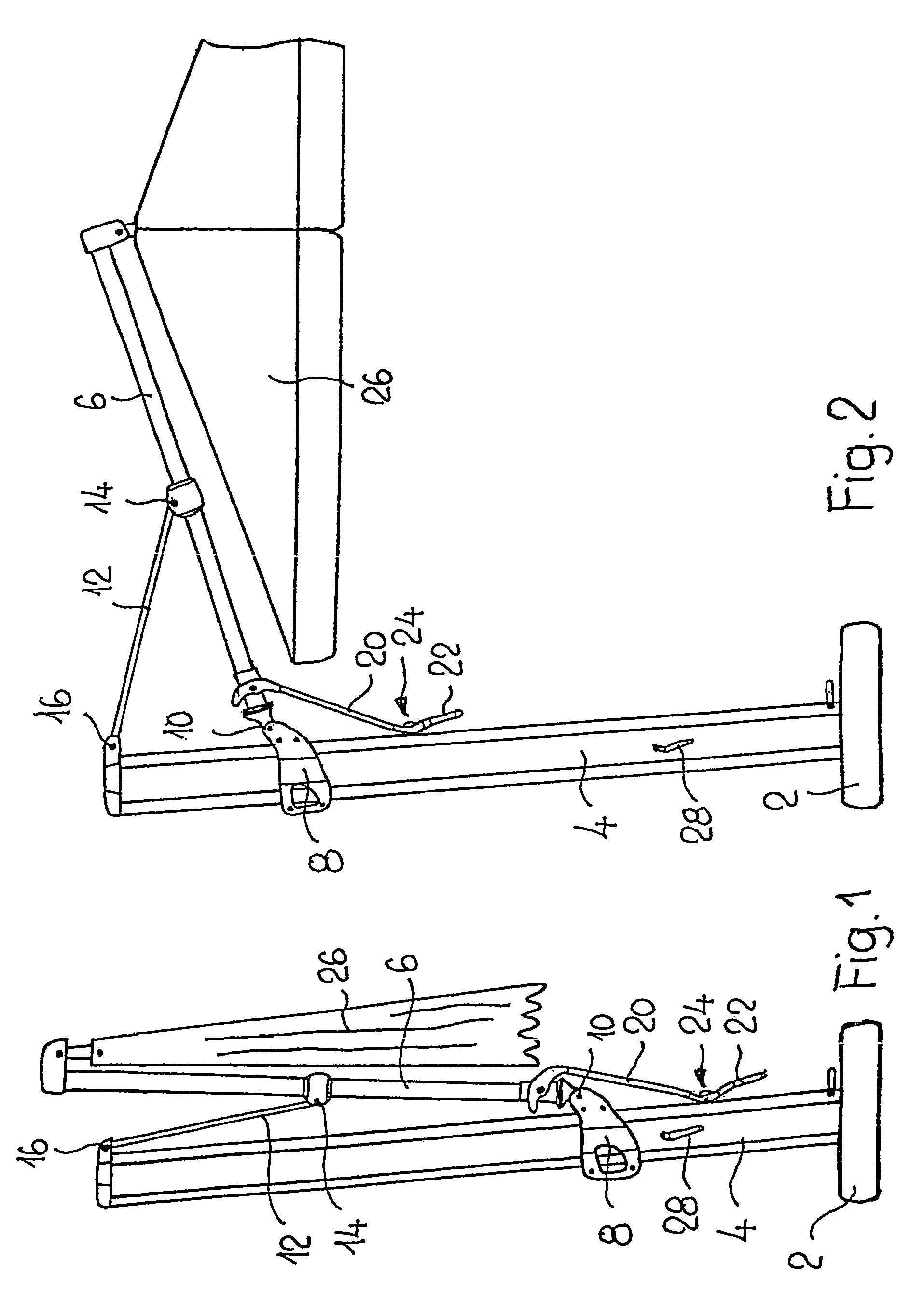
[0025]Apart from the particular configuration of the extension arm's pivoting capability, the free arm parasol illustrated in FIGS. 1 to 5 can be configured in accordance with WO 01 / 52686.

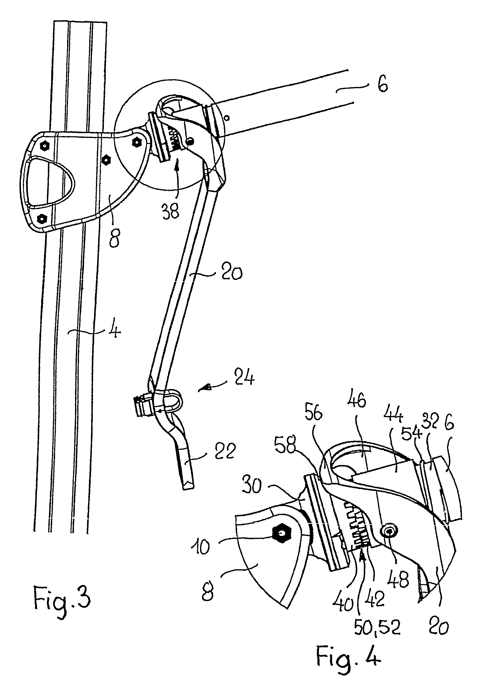
[0026]The free arm parasol illustrated in FIGS. 1 to 5 has a pole 4 which is secured, for example, in a base 2 and serves as a carrier for an extendable extension arm 6. The latter is arranged via a joint 10 on a slide 8 which is movable along the pole. The extension arm 6 is supported on the upper end of the pole via a connecting rod 12. For this purpose, the connecting rod 12 is connected, on the one hand, to the extension arm 6 via a joint 14 between the two ends of the extension arm, and, on the other hand, is connected to the upper end of the pole via a further joint 16. The pivoting of the extension arm 6 about its axis 18 is carried out with the aid of a guide rod 20. The latter has, on its lower region, a handle 22 and a retaining device 24, the latter serving to retain the guide rod 20 on ...


PUM


Abstract

The invention relates to an extension arm (6) that is arranged on a carrier (4) in such a way that it can pivot about the axis (18) thereof by means of a steering rod (20), and can be blocked in the pivoted position. Said steering rod (20) is arranged on a sleeve (44) that can be pivoted about the extension arm (6), can engage with the extension arm in different rotational angle positions, and can be directly or indirectly blocked on the carrier. According to the invention, a first coupling part (40) fixed to the extension arm (6) co-operates with a second coupling part (42) arranged on the sleeve (44) and acting in the axial direction. Furthermore, the steering rod (20) comprises a supporting element (56) that co-operates with a counterpart (58) arranged on the extension arm (6), in order to displace the second coupling part (42) in the axial direction by means of the steering rod (20). In this way, the extension arm can be pivoted and blocked in a simple manner with one hand.

Description

[0001]This application claims priority of PCT application PCT / CH2004 / 000436 having a priority date of Aug. 22, 2003, the disclosure of which is hereby incorporated herein by reference.FIELD OF THE INVENTION[0002]The invention relates to an extension arm for a free arm parasol, pivotably arranged about its axis on a carrier.BACKGROUND OF THE INVENTION[0003]An extension arm of the type mentioned at the beginning, pivotably arranged about its axis on a carrier, is known, for example, from WO 01 / 52686, in which the extension arm is configured as an extendable free arm and the carrier is configured as a pole of a free arm parasol. For optimum use of shade as the position of the sun changes, not only can the pole be rotated about its own axis, but, in particular, the extension arm can also be pivoted about its axis, so that the parasol can be brought into a corresponding oblique position and can be retained there. For this purpose, a guide rod is attached in an articulated manner to a sle...

Claims


Application Information

Patent Timeline
Patent Type & Authority Patents(United States)
IPC IPC(8): A47F5/00A45B11/00A45B17/00A45B23/00A45B25/00A47F7/00F16M11/00F16M13/00F16C11/10
CPCA45B23/00F16C11/10A45B2023/0012A45B2023/0037A45B2023/0043A45B2023/0025
Inventor GLATZ, GUSTAV ADOLF
Owner GLATZ AG
Why Eureka
Try Eureka