MEMS microphone

A technology for microphone and sound detection, which is applied to sensor components, microelectronic microstructure devices, sensors, etc., and can solve problems such as mechanical load sensitivity

Active Publication Date: 2019-03-26
INFINEON TECH AG
View PDF9 Cites 3 Cited by
  • Summary
  • Abstract
  • Description
  • Claims
  • Application Information

AI Technical Summary

Problems solved by technology

However, due to the small film thickness, the film may respond sensitively to mechanical loading

Method used


Image

  • MEMS microphone
  • MEMS microphone
  • MEMS microphone

Examples


Embodiment Construction

[0009] The term "exemplary" is used herein to mean "serving as an example, as an example, or for illustration." Every implementation or configuration described herein as "example" is not necessarily to be construed as preferred or advantageous over other implementations or configurations.

[0010] In this application, "flat" means a geometric shape of a component that has an extension along a first spatial direction and a second spatial direction orthogonal to the first spatial direction compared to along the first and second spatial directions. The extension of the orthogonal third spatial direction is larger by more than one order of magnitude, optionally by more than two orders of magnitude, further optionally by more than three orders of magnitude. The third spatial direction can also be referred to as the thickness direction of the component.

[0011] The conductive material in the present application may have a conductivity greater than 10S / m, such as greater than 10 2...


PUM


Abstract

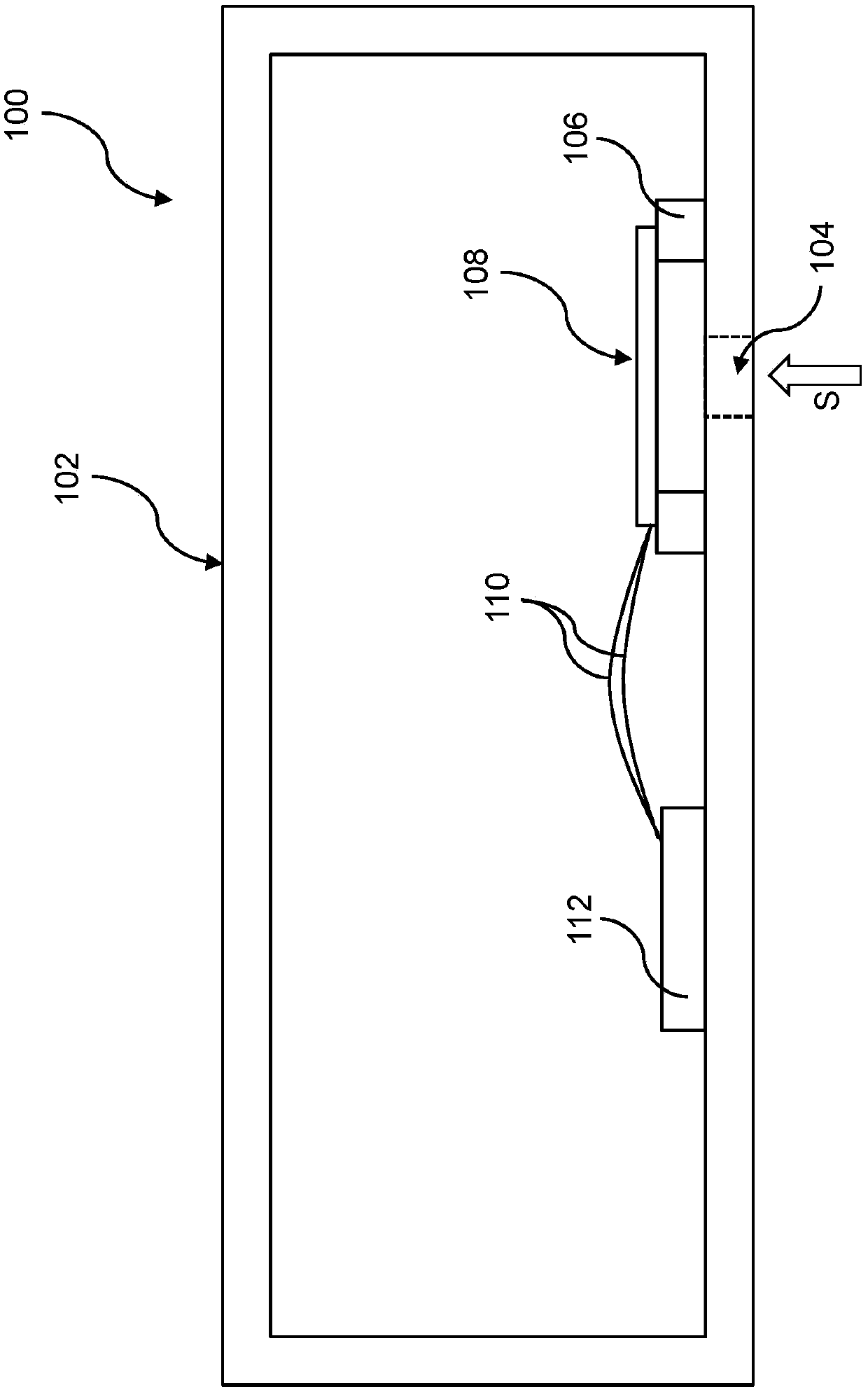
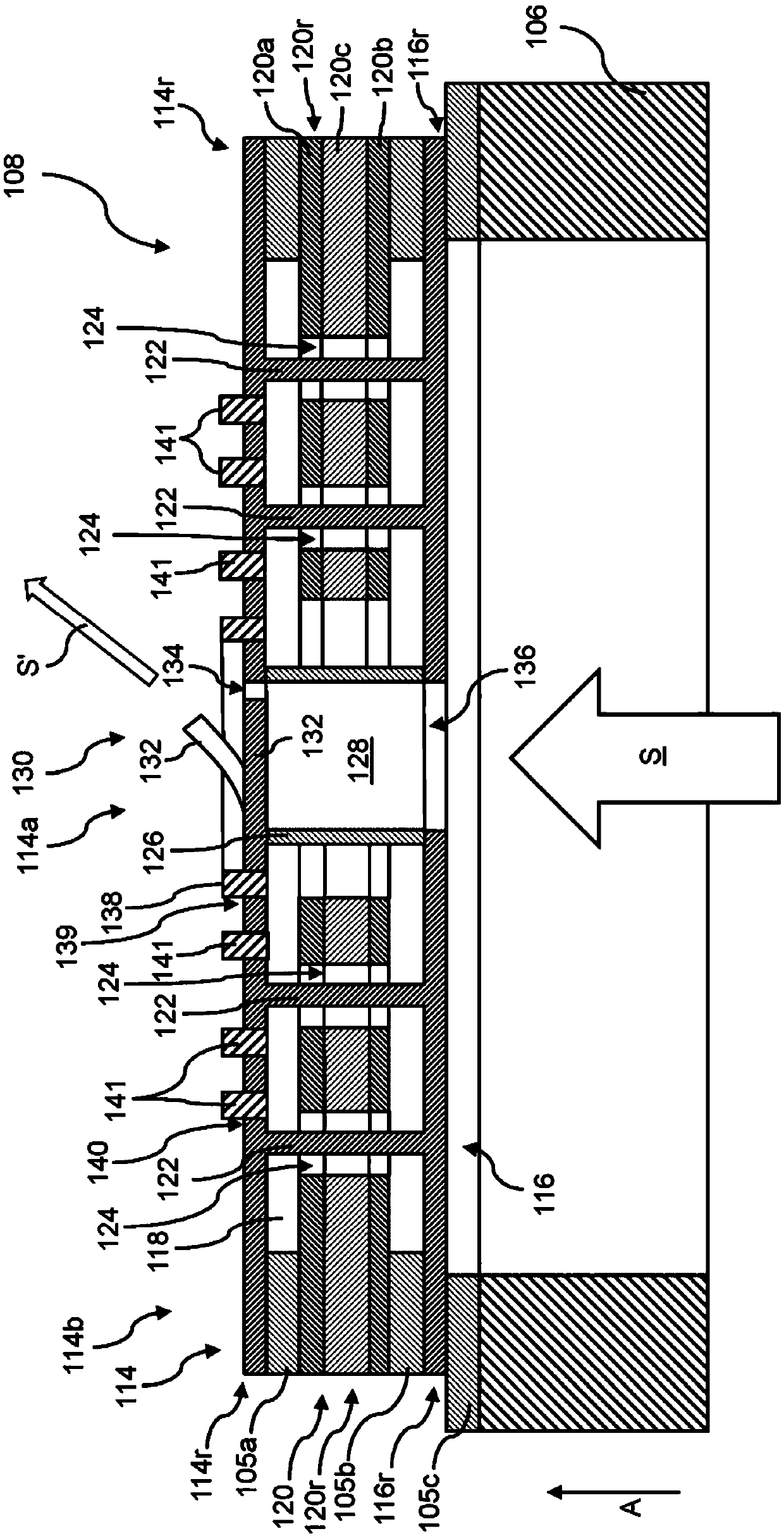
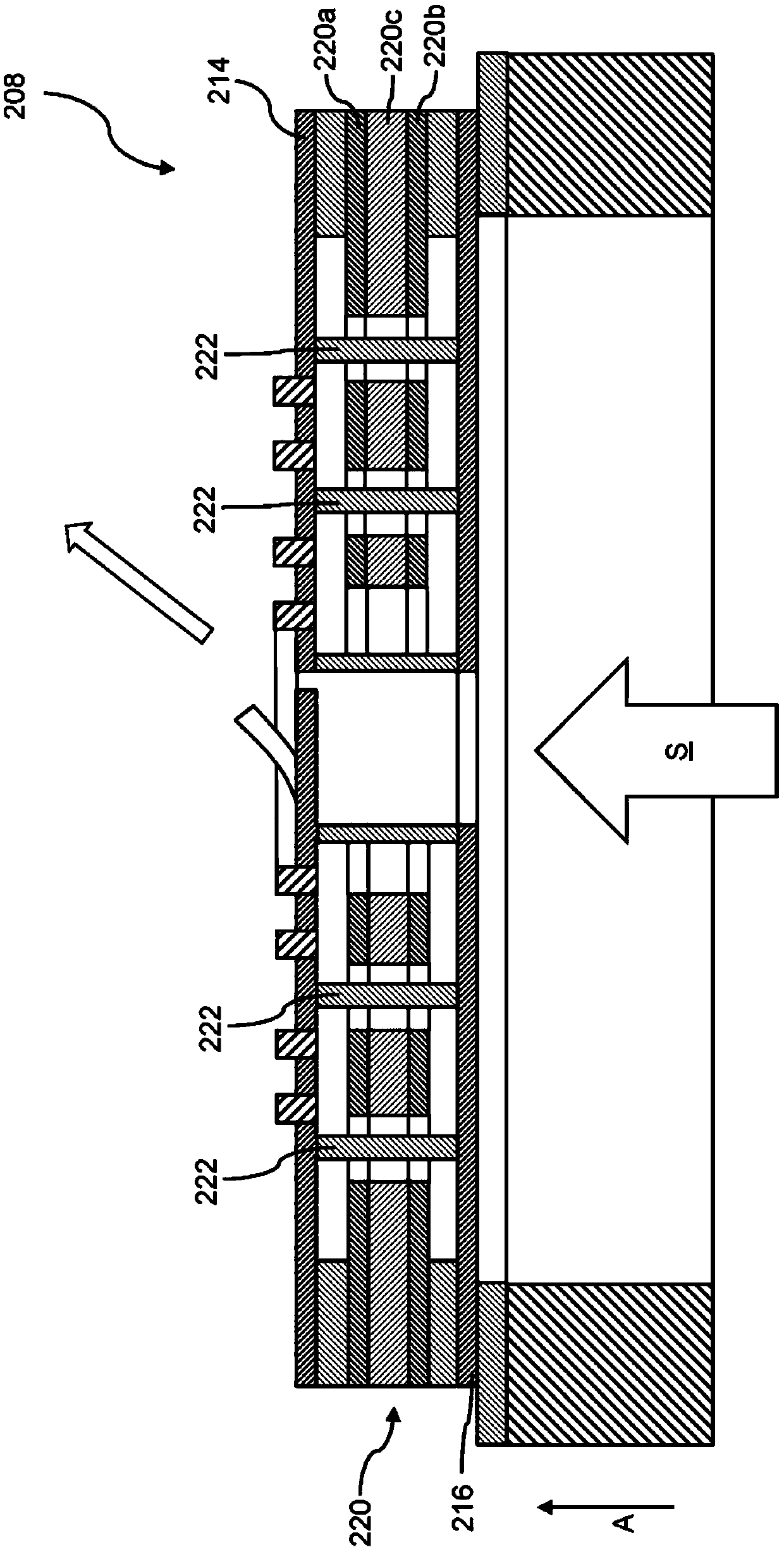
The invention relates to an MEMS microphone, and the MEMS microphone includes a sound detection unit having a first membrane, a second membrane arranged at a distance from the first membrane, a low-pressure region arranged between the first membrane and the second membrane, a gas pressure that is reduced in relation to normal pressure being present in said low-pressure region, a counter electrodearranged in the low-pressure region, and a sound through-hole, which extends through the sound detection unit in a thickness direction of the sound detection unit; and a valve provided at the sound through-hole, said valve being configured to adopt a plurality of valve states, wherein a predetermined degree of transmission of the sound through-hole to sound is assigned to each valve state.

Description

technical field [0001] A number of implementations relate generally to MEMS microphones. Background technique [0002] MEMS microphones play a central role in today's communication technologies. These MEMS microphones generally have a membrane that can be displaced by the sound to be detected, the displacement of the membrane being measured by suitable readout circuitry. For sensitive sound detection, it may be necessary for the membrane to have a very small thickness. However, due to the small film thickness, the film may react sensitively to mechanical loads. Such mechanical loading can be induced in particular by high-intensity sound waves, ie by high sound pressure. Contents of the invention [0003] According to various embodiments, there is provided a MEMS microphone, which may include: a sound detection unit and a valve. The acoustic detection may include: a first membrane; a second membrane spaced apart from the first membrane; a low pressure region provided be...

Claims


Application Information

Patent Timeline
IPC IPC(8): H04R19/04
CPCH04R19/04H04R2201/003H04R1/2807H04R19/005B81B7/02B81B2203/04B81B2201/0257B81B2203/0127
Inventor A·德厄U·克鲁宾G·梅茨格-布吕克尔J·斯特拉塞J·瓦格纳A·沃瑟
Owner INFINEON TECH AG
Why Eureka
Try Eureka