MEMS (micro electro mechanical system) microphone structure and manufacturing method of MEMS microphone structure

A manufacturing method and microphone technology, which is applied in the direction of semiconductor electrostatic transducers, electrostatic transducer microphones, sensors, etc., can solve the problems of vibrating film falling off and easy damage to the upper electrode, and achieve the effect of avoiding falling off and not being easily damaged

Active Publication Date: 2013-09-04
SHANGHAI INTEGRATED CIRCUIT RES & DEV CENT
View PDF6 Cites 52 Cited by
  • Summary
  • Abstract
  • Description
  • Claims
  • Application Information

AI Technical Summary

Problems solved by technology

A problem with this method is that when the release process is performed to remove the dielectric layer between the vibrating membrane and the back plate to form an air gap, the release process time needs to be strictly controlled. If the process time is too long, the dielectric la...

Method used


Image

  • MEMS (micro electro mechanical system) microphone structure and manufacturing method of MEMS microphone structure
  • MEMS (micro electro mechanical system) microphone structure and manufacturing method of MEMS microphone structure
  • MEMS (micro electro mechanical system) microphone structure and manufacturing method of MEMS microphone structure

Examples


Embodiment Construction

[0044] In order to make the content of the present invention clearer and easier to understand, the content of the present invention will be further described below in conjunction with the accompanying drawings. Of course, the present invention is not limited to this specific embodiment, and general replacements known to those skilled in the art are also covered within the protection scope of the present invention.

[0045] First, the structure of the MEMS microphone of the present invention will be described.

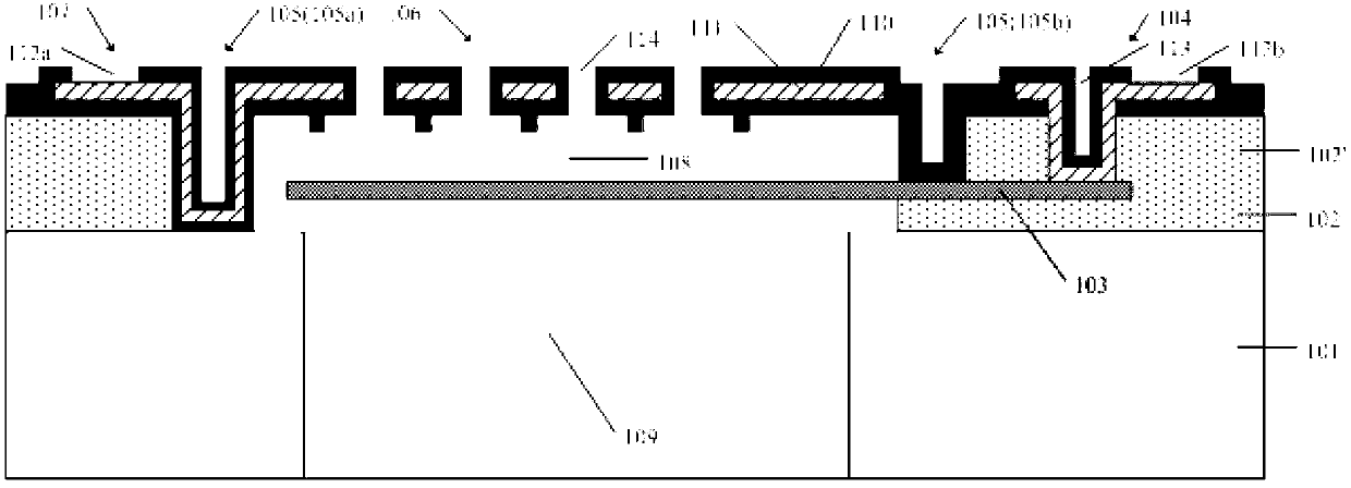
[0046]The MEMS microphone structure of the present invention includes a semiconductor substrate, a first dielectric layer, a lower electrode vibrating membrane, a lower electrode connection part and an upper electrode structure. Wherein, a cavity is formed in the substrate, and the cavity is a cavity formed by selectively removing the semiconductor substrate. The first dielectric layer is formed on the upper surface of the semiconductor substrate, and has a through hol...


PUM

PropertyMeasurementUnit
Depthaaaaaaaaaa
Diameteraaaaaaaaaa
Thicknessaaaaaaaaaa

Abstract

The invention discloses an MEMS (micro electro mechanical system) microphone structure, which comprises a semiconductor substrate, a first dielectric layer, a lower electrode vibrating membrane and an upper electrode structure, wherein the semiconductor substrate is provided with a cavity, the first dielectric layer is provided with a through hole communicated with the cavity, the lower electrode vibrating membrane is positioned above the through hole, in addition, at least one part of the lower electrode vibrating membrane is in contact with the upper surface of the first dielectric layer, the lower electrode vibrating membrane is led out from a lower electrode connecting part, the upper electrode structure is provided with an insulating layer and comprises an annular support structure, a backboard and an upper electrode connecting part, the backboard is provided with a plurality of through holes, at least one part of the annular support structure downwards extends to the lower electrode vibrating membrane, the rest parts of the annular support structure downwards extend to the substrate, the backboard is hung above the lower electrode vibrating membrane through the annular support structure, in addition, an air gap is formed between the backboard and the lower electrode vibrating membrane, and an upper electrode is embedded in the insulating layer of the backboard and is led out from the upper electrode connecting part. The MEMS microphone structure has the advantage that the damage or the falling of the upper electrode and the vibrating membrane in the release process can be avoided.

Description

technical field [0001] The invention relates to the technical field of micro-electro-mechanical systems, in particular to a MEMS microphone structure and a manufacturing method thereof. Background technique [0002] Microphones are divided into dynamic microphones and condenser microphones. The traditional dynamic microphone consists of a coil, a diaphragm and a permanent magnet. It is based on the principle that the movement of the coil in a magnetic field generates an induced current; while the main structure of a capacitive microphone is two capacitive plates, namely the diaphragm (Diaphragm ) and the backplate (Backplate), its working principle is that the sound pressure causes the deformation of the diaphragm, resulting in a change in the capacitance value, which is converted into an electrical signal output. [0003] MEMS microphones are by far one of the most successful MEMS products. MEMS microphone is a microphone manufactured by surface processing or bulk silicon...

Claims


Application Information

Patent Timeline
IPC IPC(8): H04R19/04H04R31/00
CPCH04R19/04H04R19/005H04R31/00
Inventor 袁超康晓旭左青云
Owner SHANGHAI INTEGRATED CIRCUIT RES & DEV CENT
Why Eureka
Try Eureka