Microphone with Reduced Parasitic Capacitance

a microphone and parasitic capacitance technology, applied in the field of microphones, can solve the problems of increasing the total harmonic distortion (thd) and the microphone sensitivity is reduced

Active Publication Date: 2009-08-13
INVENSENSE
View PDF4 Cites 51 Cited by
  • Summary
  • Abstract
  • Description
  • Claims
  • Application Information

AI Technical Summary

Benefits of technology

[0006]In some embodiments, the diaphragm may have an outer portion and the at least one trench may substantially align with the outer portion of the diaphragm. The diaphragm may have springs formed in an outer portion of the diaphragm. The springs couple the diaphragm to the SOI wafer. The diaphragm may have an area radially inward from the springs and the backplate may have an area radially inward from the at least one trench. The diaphragm area and the backplate area may be substantially the same size. The dia

Problems solved by technology

This parasitic capacitance decreases the sensitivity of the microphone and increases its tota

Method used


Image

  • Microphone with Reduced Parasitic Capacitance
  • Microphone with Reduced Parasitic Capacitance
  • Microphone with Reduced Parasitic Capacitance

Examples


Embodiment Construction

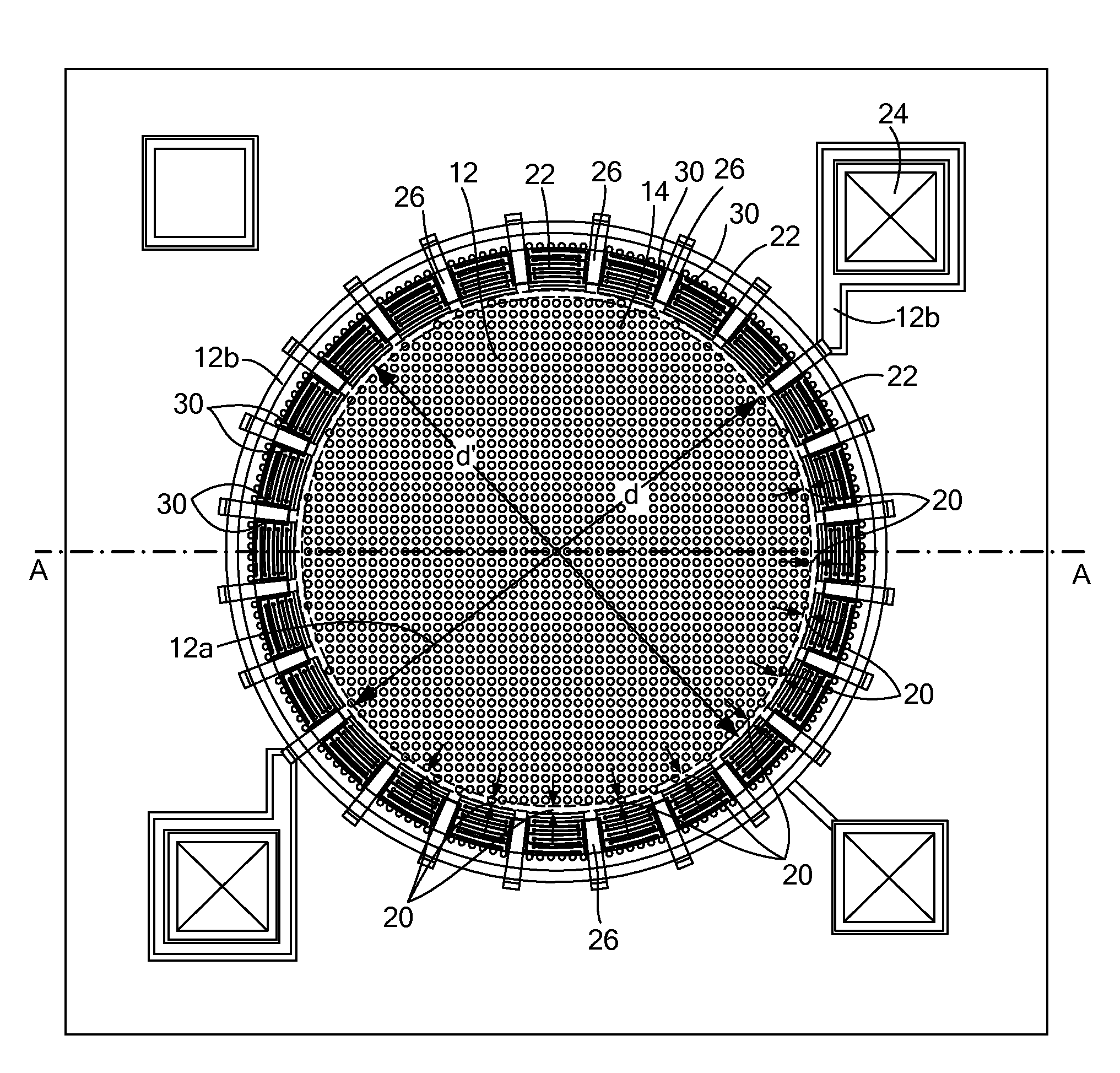
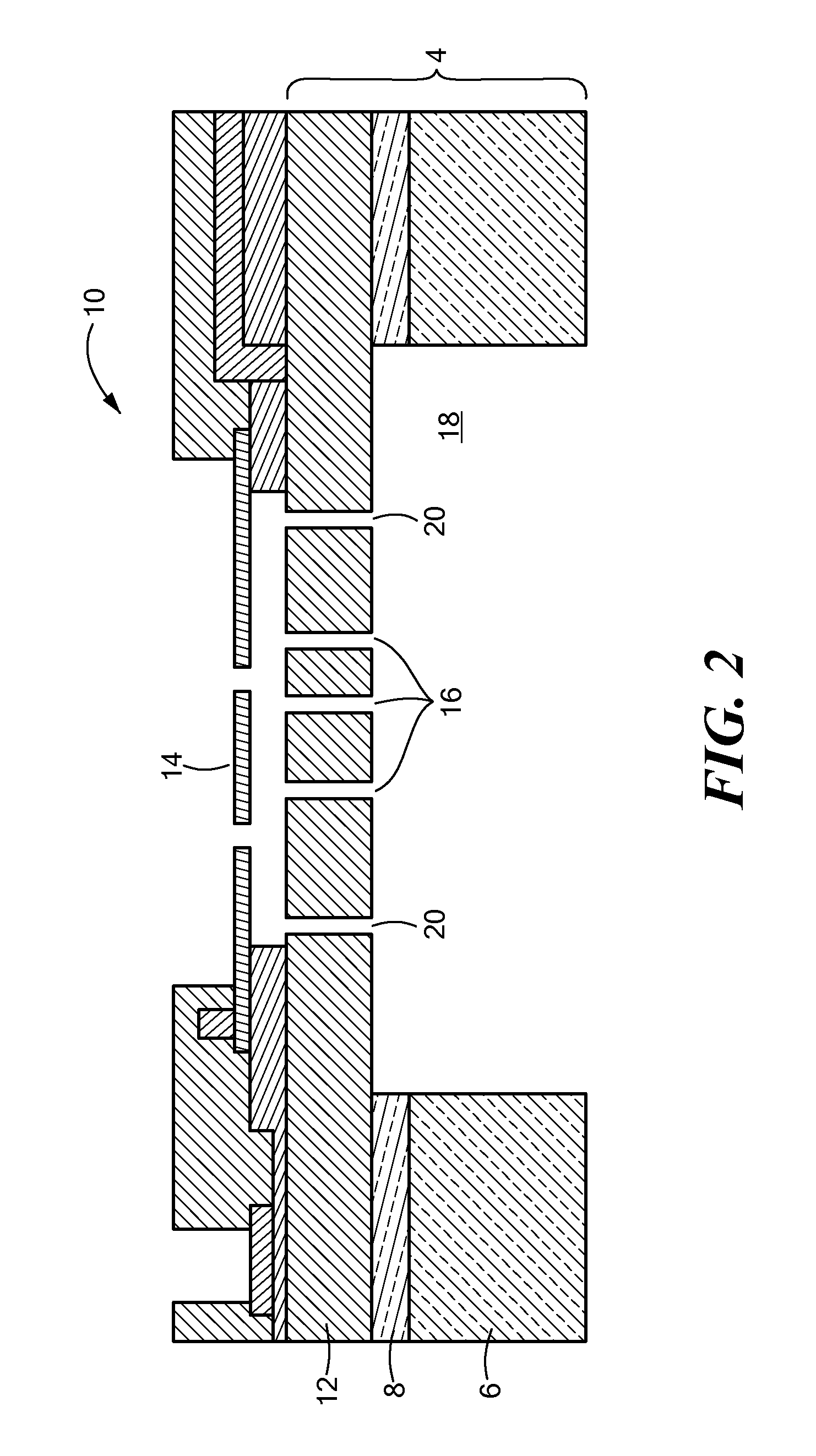
[0018]In illustrative embodiments, the diaphragm and backplate of a MEMS microphone are configured in such a manner to reduce the parasitic capacitance between these two components. This is accomplished by using at least one trench or gap in the backplate to isolate the active sensing area from the static portion of the backplate. The active backplate sensing area is formed to have about the same size and shape as the movable, inner portion of the diaphragm. This configuration substantially eliminates the parasitic capacitance from the static portion of the backplate, in some embodiments, reducing the current diaphragm-to-backplate parasitic capacitance by as much as seven times, thus increasing the signal sensitivity and reducing the total harmonic distortion (THD) in MEMS microphones. Details of illustrative embodiments are discussed below.

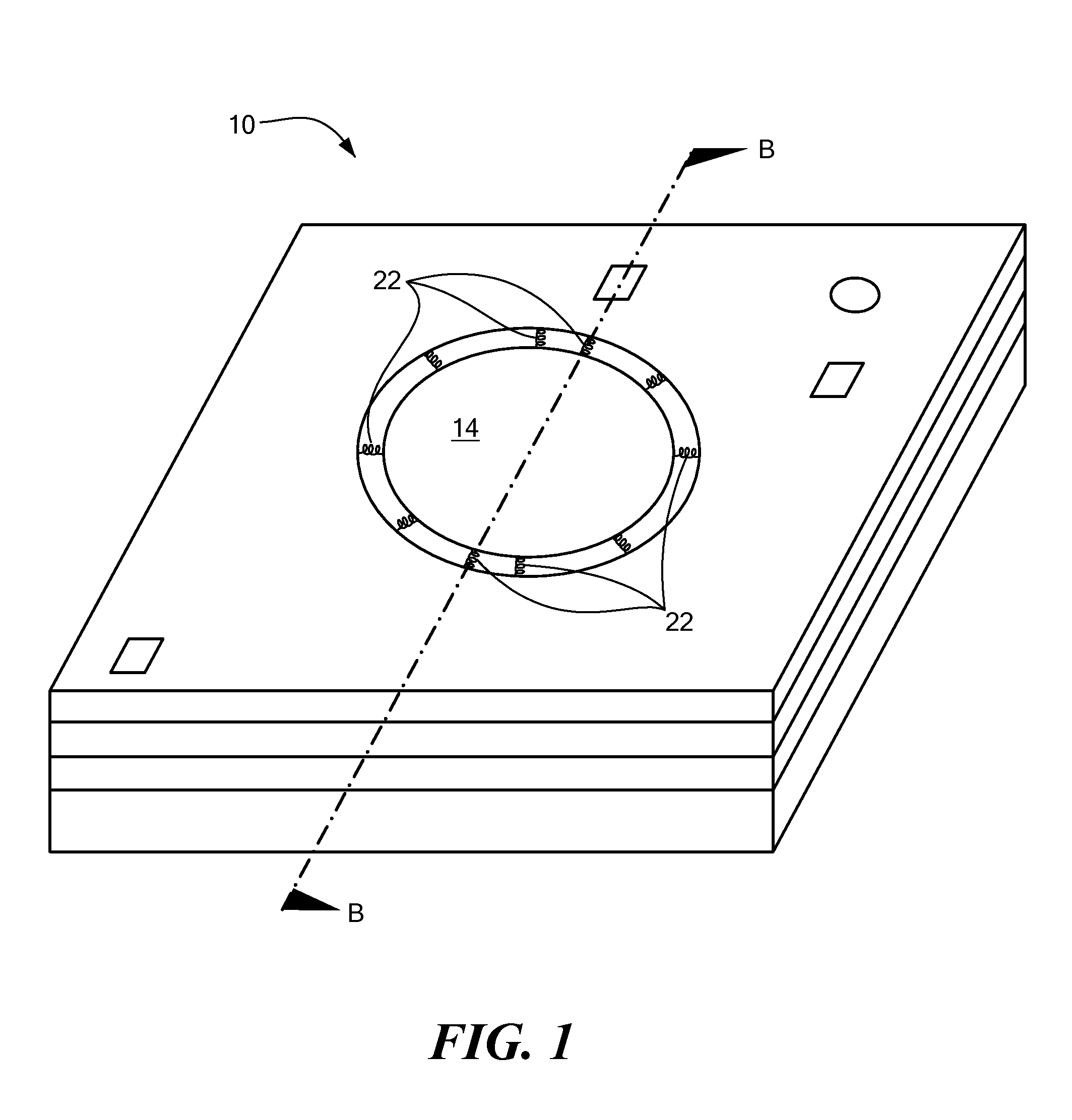
[0019]FIG. 1 schematically shows a top, perspective view of an unpackaged microelectromechanical system (MEMS) microphone 10 (also referred to ...


PUM


Abstract

A MEMS microphone has an SOI wafer, a backplate formed in a portion of the SOI wafer, and a diaphragm adjacent to and movable relative to the backplate. The backplate has at least one trench that substantially circumscribes a central portion of the backplate.

Description

CROSS-REFERENCE TO RELATED APPLICATIONS[0001]The present application is a continuation-in-part of U.S. patent application Ser. No. 12 / 133,599 filed Jun. 5, 2008, entitled MICROPHONE WITH ALIGNED APERTURES, which claims priority to U.S. provisional patent application Ser. No. 60 / 942,315, filed Jun. 6, 2007, entitled MICROPHONE WITH ALIGNED APERTURES, each disclosure of which is incorporated herein by reference in its entirety.FIELD OF THE INVENTION[0002]The invention generally relates to microphones and, more particularly, the invention relates to MEMS microphones having reduced parasitic capacitance.BACKGROUND OF THE INVENTION[0003]A conventional MEMS microphone typically has a static substrate / backplate and a flexible diaphragm that together form a variable capacitor. In operation, audio signals cause the movable diaphragm to vibrate, thus varying the distance between the diaphragm and the backplate and producing a changing capacitance. The backplate often is formed from a portion ...

Claims


Application Information

Patent Timeline
IPC IPC(8): H04R11/04H01L21/762H01L29/84
CPCH04R1/222H04R2499/11H04R19/04H04R19/005
Inventor ZHANG, XINCHEN, THOMASBHARATAN, SUSHILKHENKIN, ALEKSEY S.
Owner INVENSENSE
Why Eureka
Try Eureka