Base Station
A technology for base stations and cleaning tanks, used in carpet cleaning, floor cleaning, cleaning equipment, etc., can solve the problems of difficult cleaning, inconvenient cleaning, complex structure of base stations, etc., and achieve the effect of improving user experience
- Summary
- Abstract
- Description
- Claims
- Application Information
AI Technical Summary
Problems solved by technology
Method used
Image

Examples
no. 1 example
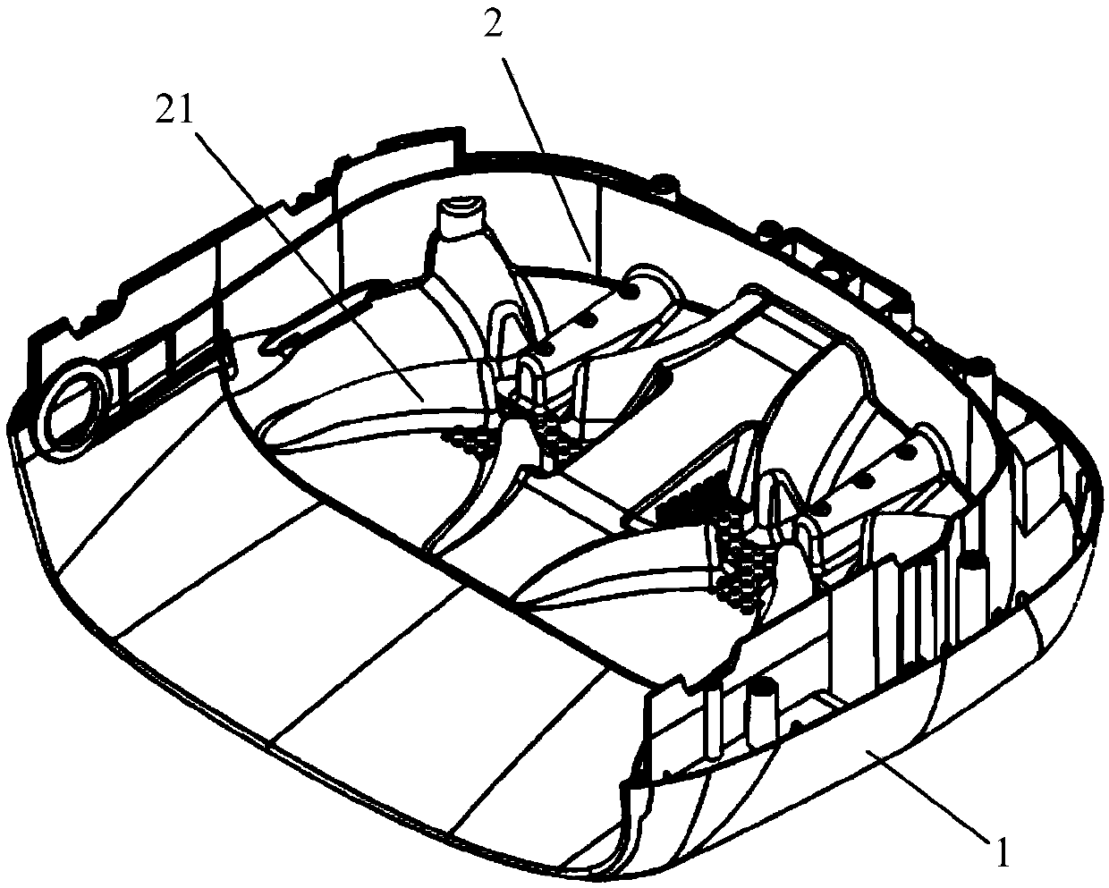
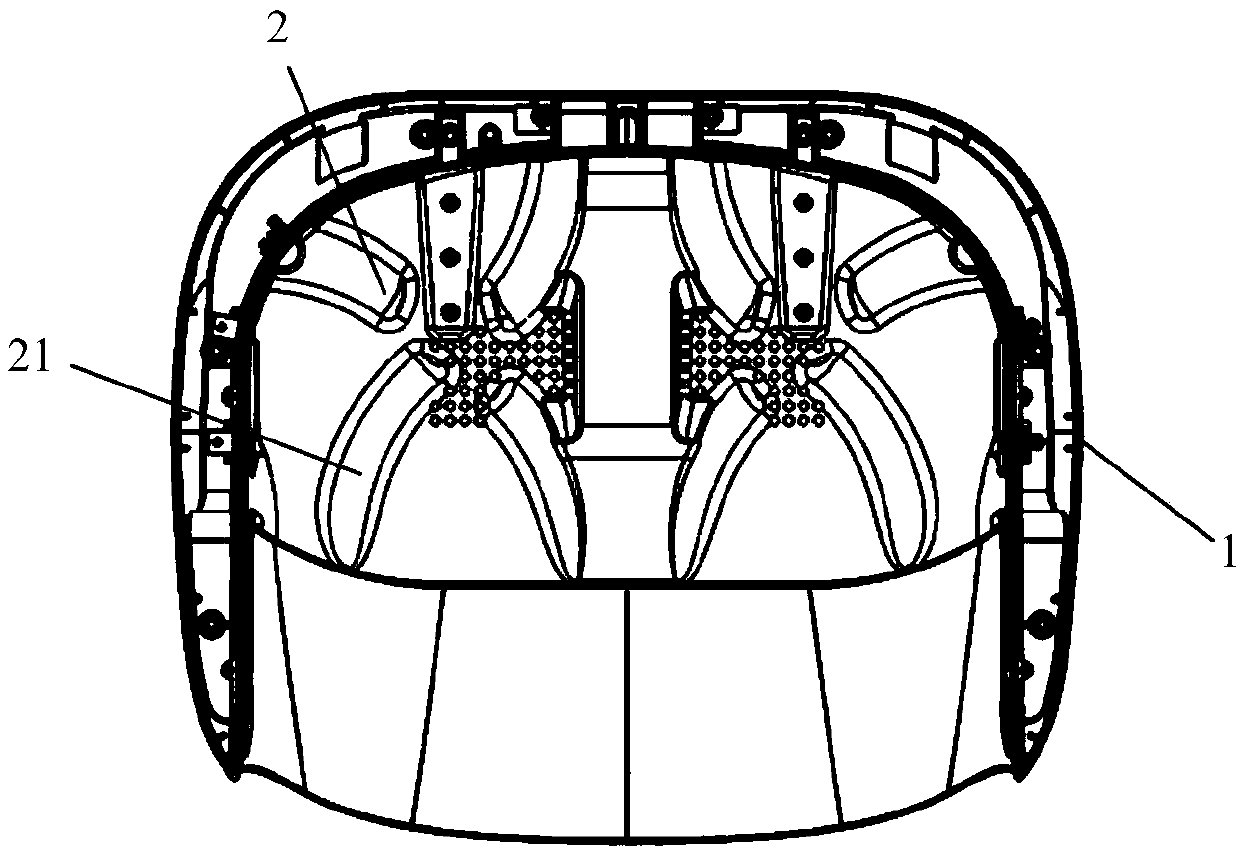
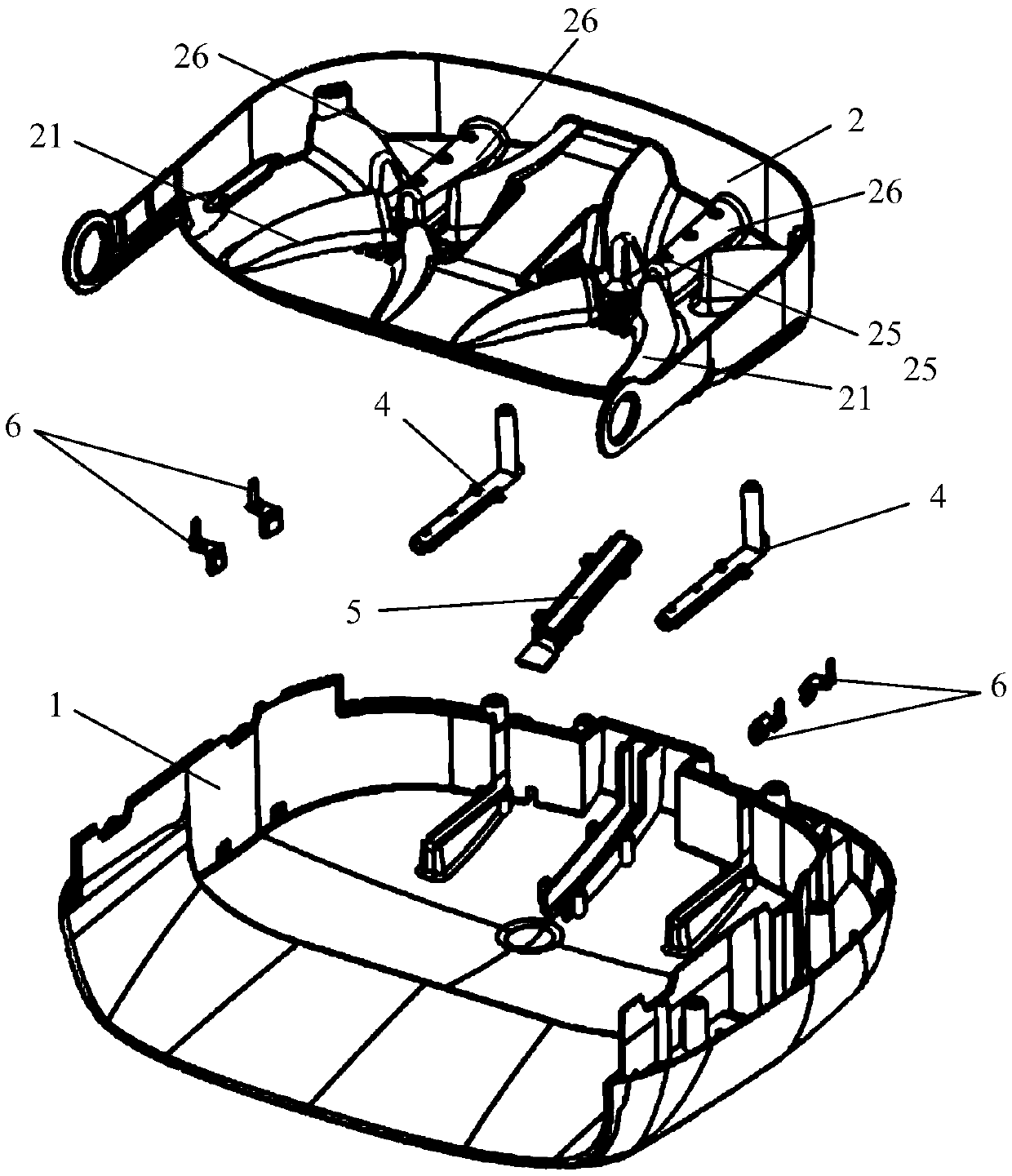
[0084] like Figure 1 to Figure 17 The base station of the first embodiment of the present invention is shown.
[0085] like Figure 1 to Figure 4 As shown, the base station includes a base station base 1 and a cleaning tank 2. The cleaning tank 2 and the base station base 1 are detachably connected. The cleaning tank 2 is provided with a liquid inlet structure, a liquid discharge structure, and a raised portion 21. The raised portion 21 is used for Scratch and decontaminate the mopping parts of the cleaning robot. Among them, the liquid inlet structure is used to provide cleaning water to the cleaning tank 2, and the liquid discharge structure is used to discharge the cleaning water in the cleaning tank 2 out of the cleaning tank 2, for example, the cleaning water after cleaning the mopping parts of the cleaning robot is discharged out of the cleaning tank 2. The raised portion 21 is a raised structure protruding from the bottom of the cleaning tank 2 . The raised portion...
no. 2 example
[0128] Figure 18 Shown is the base station provided by the second embodiment of the present invention. The difference from the first embodiment is that the anti-overflow contact piece 6 is installed on the base station base 1 , and the anti-overflow water port 28 in the first embodiment is no longer provided on the cleaning tank 2 . The sewage is filtered through the cleaning tank 2 and flows into the base station base 1. When there is a problem with water absorption, the water will gradually overflow and soak into the anti-overflow contact piece 6, thereby realizing the anti-overflow function of the base station.
[0129] For example, the anti-overflow contact piece 6 is arranged in the sewage collection chamber and on the inner side wall of the base station base 1 . In the vertical direction, the anti-overflow contact piece 6 is located below the overflow water level of the base station base 1 and above the lowest point of the water level of the base station base 1 .
[0...
no. 3 example
[0133] Figure 19 and Figure 20 Shown is the base station provided by the third embodiment of the present invention. The difference from the first embodiment is that in the third embodiment, the filter hole 24 of the first embodiment is not provided on the cleaning tank 2 . In the third embodiment, the base station includes a base station base 1 and a cleaning tank 2, the cleaning tank 2 and the base station base 1 are detachably connected, and the cleaning tank 2 is provided with a liquid inlet structure, a liquid discharge structure and a protrusion, and the protrusion is used for It is used to scrape and decontaminate the mopping parts of the cleaning robot. Wherein, the liquid inlet structure is the water spray port 25 , and the liquid discharge structure is the water suction port 230 .
[0134] Optionally, an anti-overflow contact piece 6 is also provided on the cleaning tank 2 , and the anti-overflow contact piece 6 is arranged on the inner surface of the side wall o...
PUM
 Abstract
Description
Claims
Application Information
 - R&D
- Intellectual Property
- Life Sciences
- Materials
- Tech Scout
- Unparalleled Data Quality
- Higher Quality Content
- 60% Fewer Hallucinations
Browse by: Latest US Patents, China's latest patents, Technical Efficacy Thesaurus, Application Domain, Technology Topic, Popular Technical Reports.
© 2025 PatSnap. All rights reserved.Legal|Privacy policy|Modern Slavery Act Transparency Statement|Sitemap|About US| Contact US: help@patsnap.com