Columnar valve element

A valve core, columnar technology, applied in valve devices, cocks including cut-off devices, engine components, etc., can solve problems such as unfavorable use, high precision and process requirements, and reduced sealing performance, to strengthen the sealing effect and improve the structure. Strength, the effect of enhancing sealing performance

Pending Publication Date: 2019-03-29
TAIZHOU TONGSHENG BRASS
View PDF1 Cites 0 Cited by
  • Summary
  • Abstract
  • Description
  • Claims
  • Application Information

AI Technical Summary

Problems solved by technology

[0003] In order for the spool to be installed into the valve body smoothly and enable the spool to move or rotate smoothly, there is often a movable gap between the outer surface of the spool and the wall surface of the valve inner cavity, which will cause the spool and the valve body to Poor seal between
The commonly used method to improve the sealing is to install a sealing ring between the valve core and the valve body. The installation of the sealing ring often requires the installation of a slot. The setting of the slot will make the structure of the seal between the valve core and the valve body If there is a change, structural defects are likely to occur when other structures are not adjusted, which is not conducive to use. If there is no caulking groove, the sealing ring is easy to move during the movement or rotation of the valve core, resulting in a decrease in sealing performance
Or, as the application number is CN201020300360.0, the structure of the valve body and the valve core is matched and the sealant is coated on the sealing surface of the two. This method is not only complicated in process, but also easy to fit too tightly. It makes it difficult for the spool to rotate, and the relative movement after forceful rotation is easy to damage the structure of the sealant, resulting in a decrease in sealing performance.
In addition, for some valves used under high temperature conditions, it is often not possible to use sealing rings, and there is a direct metal seal between the valve core and the valve body, which requires high production precision and craftsmanship. Decreased airtightness

Method used


Image

  • Columnar valve element
  • Columnar valve element
  • Columnar valve element

Examples


Embodiment 1

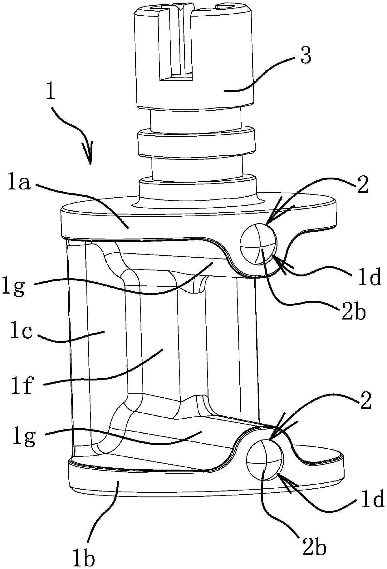
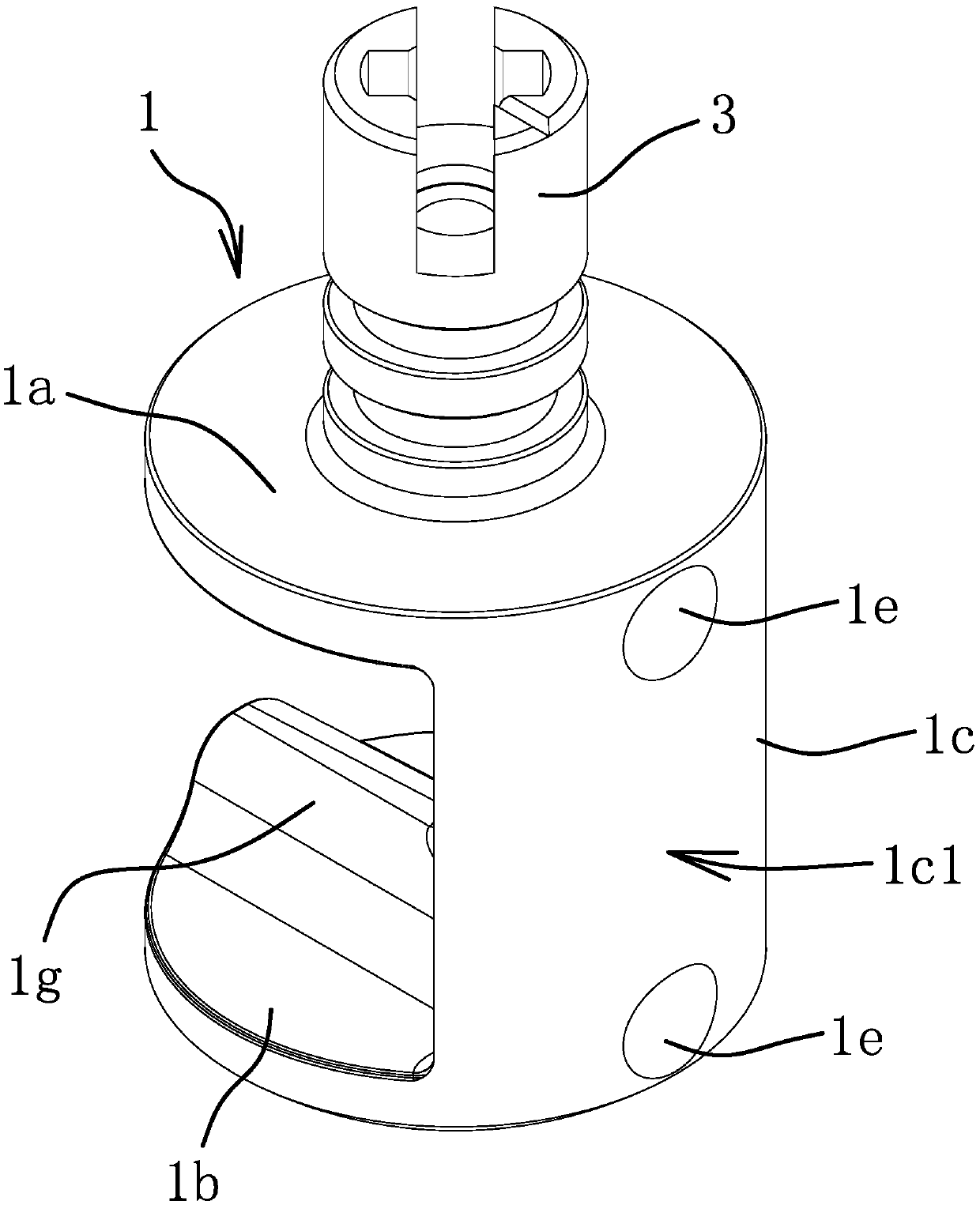
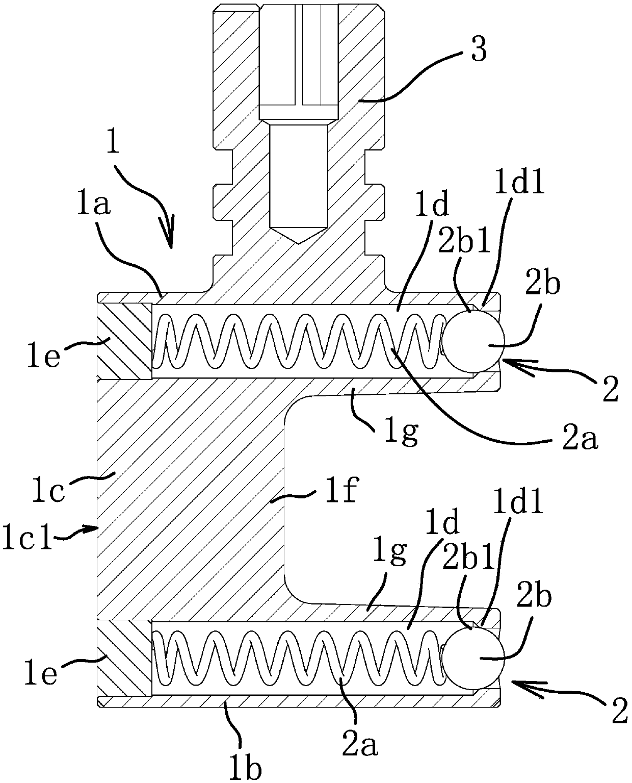
[0031] Such as Figure 1-Figure 3 As shown, a cylindrical valve core includes a body 1 and a core rod 3. The body 1 is in the shape of a "匚" and includes a circular top plate 1a, a circular bottom plate 1b, and a connection between the top plate 1a and the bottom plate 1b. Connection plate 1c. The side opposite to the connecting plate 1c on the top plate 1a and the bottom plate 1b is provided with a pressing assembly 2, and the pressing assembly 2 includes a pressing head 2b, and the pressing head 2b on the top plate 1a protrudes from the side of the top plate 1a in an elastic manner On the surface, the pressing head 2b on the bottom plate 1b protrudes from the side surface of the bottom plate 1b in an elastic manner. The core rod 3 is integrally connected or separately fixed on the top plate 1a, and a communication port is formed between the top plate 1a and the bottom plate 1b. The cross section of the connecting plate 1c is convex arched, the two sides of the connecting p...

Embodiment 2

[0035] The main structure of the spool is the same as that of the first embodiment, and the structure of the pressing assembly 2 is different from that of the first embodiment. The pressing assembly 2 includes an elastic sheet, which is in the shape of a "J" or U. The installation hole 1d is a blind hole, the open end of the elastic sheet is fixed in the installation hole 1d, and the closed end of the elastic sheet extends out of the installation hole 1d. In this embodiment, the closed end of the elastic sheet is the pressing head 1b. When the valve core is inserted into the valve body 4, the outer end surface of the pressing head 2b is against the cavity wall surface of the inner cavity of the valve body 4, and the elastic sheet is elastically deformed and the resulting force acts on the body 1, so that the sealing surface 1c1 abuts against the wall surface of the inner cavity of the valve body 4 to form a seal, and under the action of the pressing component 2, the sealing eff...


PUM


Abstract

The invention provides a columnar valve element, and belongs to the technical field of valves. The problem that an existing valve element is not good in sealing performance is solved. The columnar valve element comprises a body in a horizontal right-angle-n shape. The body comprises a round top plate, a round bottom plate and a connecting plate connected between the top plate and the bottom plate.The outer side face of the connecting plate is a sealing face in an arc columnar shape. The side, opposite to the connecting plate, of the top plate and / or the bottom plate is provided with an ejecting assembly. The ejecting assembly comprises an ejecting head. The ejecting head protrudes out of the side surface of the top plate and / or the bottom plate elastically. The columnar valve element hasthe advantage that the sealing performance can be enhanced.

Description

technical field [0001] The invention belongs to the technical field of valves and relates to a columnar valve core. Background technique [0002] The valve is used to control the medium in the pipeline, and it is an overall mechanical product with a movable mechanism. Valves are classified according to structure, including gate valves, ball valves, butterfly valves, diaphragm valves, etc. The structure of the valve includes a valve body and a valve core. The valve body is provided with an inner cavity, and the valve core is installed in the inner cavity of the valve body. By moving or rotating the valve core, the valve can be used under different flow rates. [0003] In order for the spool to be installed into the valve body smoothly and enable the spool to move or rotate smoothly, there is often a movable gap between the outer surface of the spool and the wall surface of the valve inner cavity, which will cause the spool and the valve body to The seal between them is not ...

Claims


Application Information

Patent Timeline
Patent Type & Authority Applications(China)
IPC IPC(8): F16K5/04F16K5/18
CPCF16K5/0407F16K5/187
Inventor 詹征
Owner TAIZHOU TONGSHENG BRASS
Why Eureka
Try Eureka