
Ultrasonic receiver, ultrasonic transmitter and ultrasonic indoor positioning system

A technology of a transmitting device and a receiving device, which is applied in the field of indoor positioning, can solve problems such as multipath effect and receiving dead zone, and achieve the effect of avoiding receiving dead zone and multipath effect.

Inactive Publication Date: 2019-03-29
HEBEI UNIVERSITY OF SCIENCE AND TECHNOLOGY
View PDF5 Cites 2 Cited by
  • Summary
  • Abstract
  • Description
  • Claims
  • Application Information

AI Technical Summary

Problems solved by technology

[0003] In view of this, an embodiment of the present invention provides an ultrasonic receiving device, an ultrasonic transmitting device, and an ultrasonic indoor positioning system to solve the problems of receiving dead zones and multipath effects in ultrasonic positioning in the prior art

Method used


Image

  • Ultrasonic receiver, ultrasonic transmitter and ultrasonic indoor positioning system
  • Ultrasonic receiver, ultrasonic transmitter and ultrasonic indoor positioning system
  • Ultrasonic receiver, ultrasonic transmitter and ultrasonic indoor positioning system

Examples


Embodiment Construction

[0024] In the following description, specific details such as specific system structures and technologies are presented for the purpose of illustration rather than limitation, so as to thoroughly understand the embodiments of the present invention. It will be apparent, however, to one skilled in the art that the invention may be practiced in other embodiments without these specific details. In other instances, detailed descriptions of well-known systems, devices, circuits, and methods are omitted so as not to obscure the description of the present invention with unnecessary detail.

[0025] In order to illustrate the technical solutions of the present invention, specific examples are used below to illustrate.

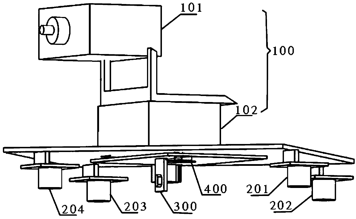
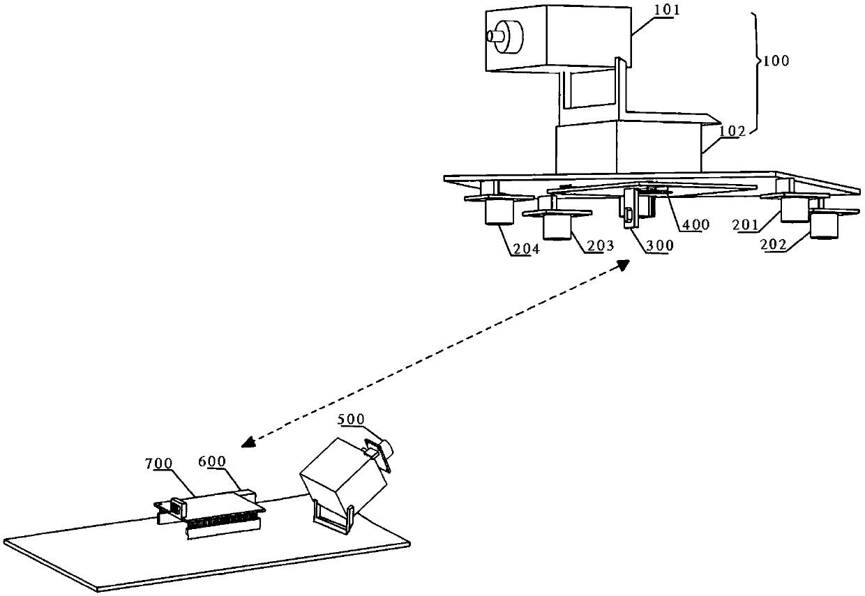
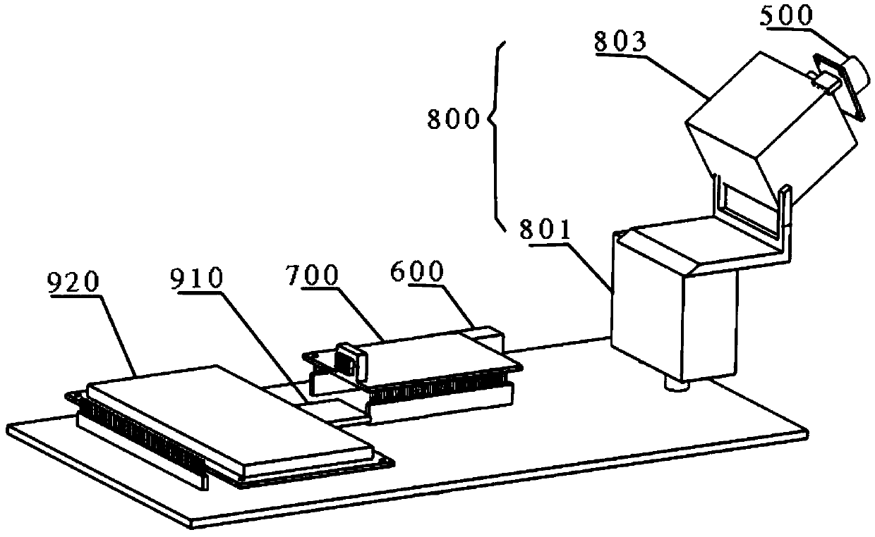
[0026] An embodiment of the present invention provides an ultrasonic receiving device, such as figure 1 As shown, the ultrasonic receiving device may include: a first rotating component 100 , ultrasonic receiving probes 201 - 204 , a timer, a first communication module...


PUM


Abstract

The invention is suitable for the technical field of indoor positioning, and provides an ultrasonic receiver, an ultrasonic transmitter and an ultrasonic indoor positioning system. The ultrasonic receiver comprises a first rotating component, at least two ultrasonic receiving probes, at least two timers, a first communication module and a first controller, wherein the first controller is used forcomputing a position of the ultrasonic transmitter according to timing information of the at least two timers, and controlling the rotation of the first rotating component according to the position. According to the ultrasonic receiver, the ultrasonic transmitter and the ultrasonic indoor positioning system which are provided by the embodiments of the invention, through the arrangement of the first rotating component, the ultrasonic receiver can adjust a rotating angle of the first rotating component in real time according to the position of the ultrasonic transmitter corresponding to the ultrasonic receiver, so that the ultrasonic receiving probe arranged on the first rotating component can keep forward orientation with the ultrasonic transmitter corresponding to the ultrasonic receivingprobe, and a receiving dead zone and a multi-path effect are avoided.

Description

technical field [0001] The invention belongs to the technical field of indoor positioning, and in particular relates to an ultrasonic receiving device, an ultrasonic emitting device and an ultrasonic indoor positioning system. Background technique [0002] With the development of science and technology, satellite positioning technology has been continuously improved. Since it is difficult for satellite signals to pass through buildings, it is difficult for satellite positioning to play a role in a closed room. Indoor positioning technology has become a research hotspot in recent years. Indoor positioning is to obtain environmental information through some sensors in the two-dimensional environment where the moving object works, and determine the coordinates and pose of the object itself after information processing. Ultrasonic positioning is widely used in indoor positioning due to the advantages of strong reflectivity, strong penetrating ability, easy energy concentration,...

Claims


Application Information

Patent Timeline
Patent Type & Authority Applications(China)
IPC IPC(8): G01C21/20G01S15/46G01S15/88
CPCG01C21/206G01S15/46G01S15/88
Inventor 张岩赵江
Owner HEBEI UNIVERSITY OF SCIENCE AND TECHNOLOGY
Learn More