Ultrasonic flaw detection device

A flaw detection device, ultrasonic technology, applied to measuring devices, material analysis using sound waves/ultrasonic waves/infrasonic waves, instruments, etc., can solve the problems of inconvenience, less freedom of movement of the probe, and easy increase of detection accuracy errors, etc., to achieve improvement The effect of improving detection accuracy, improving operation convenience, and reducing detection error

Active Publication Date: 2019-03-29
武汉瑞敏检测科技有限公司
View PDF8 Cites 6 Cited by
  • Summary
  • Abstract
  • Description
  • Claims
  • Application Information

AI Technical Summary

Problems solved by technology

[0006] The purpose of the present invention is to provide an ultrasonic flaw detection device to solve the above 1. The existing ultrasonic probes are generally fixedly installed on lifting or telescopic supports. The top surface or the side surface is in contact with the internal defects of the detection material, and it is inconvenient to operate at various angles; 2. The transducer in the existing ultrasonic probe is directly adjacent to the end of the probe, and it is impossible to ensure the performance of the detection operation. The transducer can be tightly coupled with the surface of the Bezel material, which is easy to increase the problem of detection accuracy error

Method used


Image

  • Ultrasonic flaw detection device
  • Ultrasonic flaw detection device
  • Ultrasonic flaw detection device

Examples


Embodiment Construction

[0035] The following will clearly and completely describe the technical solutions in the embodiments of the present invention with reference to the accompanying drawings in the embodiments of the present invention. Obviously, the described embodiments are only some, not all, embodiments of the present invention. Based on the embodiments of the present invention, all other embodiments obtained by persons of ordinary skill in the art without creative efforts fall within the protection scope of the present invention.

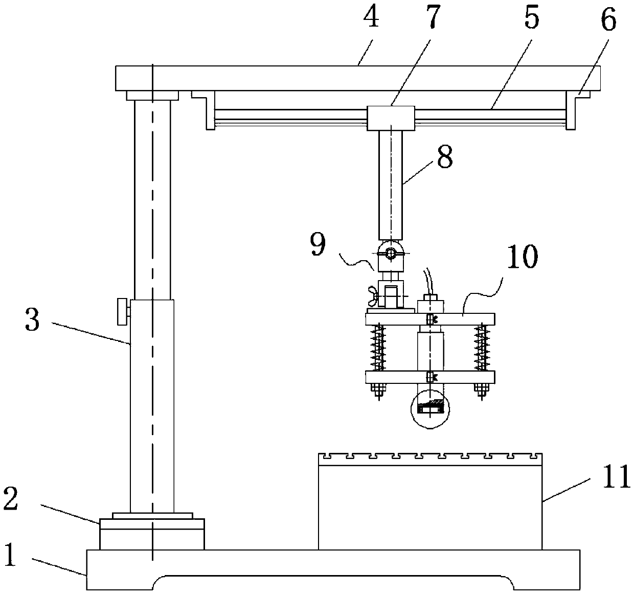
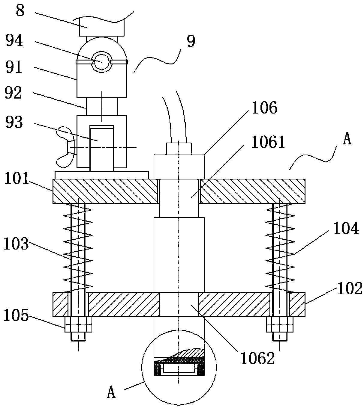
[0036] see Figure 1-7, the present invention provides a technical solution: an ultrasonic flaw detection device, comprising a device base (1), an indexing turntable (2) is fixed on the left side of the top of the device base (1), and the indexing turntable The top of (2) is vertically affixed with a telescopic support column (3), and the telescopic end top of the telescopic support column (3) is horizontally affixed with an installation beam (4), and the bottom of...


PUM


Abstract

The invention discloses an ultrasonic flaw detection device relating to the technical field of ultrasonic flaw detection. The ultrasonic flaw detection device comprises a base; an index rotary disc isfixedly arranged on the left side of the top of the base; a telescopic supporting column is vertically and fixedly connected to the top of the index rotary disc; a mounting cross beam is horizontallyand fixedly connected to the top end of the telescopic end of the telescopic supporting column; a fixed sliding rail is arranged at the bottom of the mounting cross beam; the left end and the right end of the fixed sliding rail are connected to the mounting cross beam through sliding rail connecting seats; a movable sliding sleeve is movably sleeved on the outer wall of the fixed sliding rail; afixed connecting rod is fixedly connected to the bottom of the movable sliding sleeve; the bottom of the fixed connecting rod is connected to a probe assembly through a universal hinge mechanism; a work piece clamping table is fixedly arranged on the right side of the top of the base; the work piece clamping table is located below the probe assembly; and the probe assembly comprises an upper fixedplate, a lower fixed plate, a connecting screw, a compression spring, and a double nut. According to the ultrasonic flaw detection device, the device is convenient to operate and has little detectionerror.

Description

technical field [0001] The invention relates to the technical field of ultrasonic flaw detection equipment, in particular to an ultrasonic flaw detection device. Background technique [0002] Ultrasonic flaw detection is a method for inspecting parts defects by using ultrasonic energy to penetrate deep into the metal material and pass from one section to another section, reflecting at the edge of the interface to inspect parts defects. Inside the metal, when a defect and the bottom surface of the part are encountered, reflected waves will be generated respectively, and pulse waveforms will be formed on the fluorescent screen. Based on these pulse waveforms, the position and size of the defect can be judged. [0003] There are many wave modes when ultrasonic wave propagates in the medium, the most commonly used in inspection are longitudinal wave, transverse wave, surface wave and plate wave. Use longitudinal waves to detect defects such as inclusions, cracks, shrinkage tube...

Claims


Application Information

Patent Timeline
Patent Type & Authority Applications(China)
IPC IPC(8): G01N29/22G01N29/265
CPCG01N29/22G01N29/265
Inventor 吕伟张祥瑞
Owner 武汉瑞敏检测科技有限公司
Why Eureka
Try Eureka