
Automatic compression device of cable performance testing equipment

A technology of testing equipment and pressing devices, which is applied in the direction of measuring devices, measuring device casings, and parts of electrical measuring instruments, etc., can solve the problems of low manual pressing efficiency, uncontrollable pressing force, and low degree of automation. Achieve the effects of reducing labor intensity, increasing automation, and improving work efficiency

Pending Publication Date: 2019-03-29
GUILIN UNIV OF ELECTRONIC TECH
View PDF6 Cites 0 Cited by
  • Summary
  • Abstract
  • Description
  • Claims
  • Application Information

AI Technical Summary

Problems solved by technology

[0006] In view of the above deficiencies, in order to solve the problems of low manual compression efficiency, low degree of automation, and uncontrollable compression force, the present invention provides an automatic compression device for cable performance testing equipment

Method used


Image

  • Automatic compression device of cable performance testing equipment
  • Automatic compression device of cable performance testing equipment
  • Automatic compression device of cable performance testing equipment

Examples


Embodiment 1

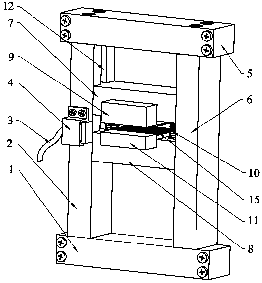
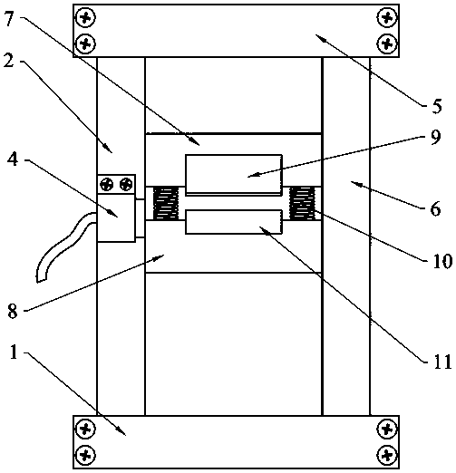
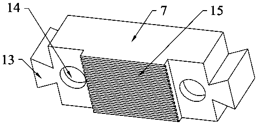
[0026] Please refer to Figure 1 to Figure 4 , the preferred embodiment of the present invention provides an automatic compression device for cable performance testing equipment, including a square frame body, the square frame body is vertically arranged, and the two sides of the square frame body are oppositely provided with chute 12, the square frame body The frame body is provided with an upper compression block 7 and a lower compression block 8 from top to bottom, the upper compression block 7 and the lower compression block 8 have the same structure, and the two ends of the upper compression block 7 and the lower compression block 8 are respectively The sliding block 13 is matched and installed in the chute 12 on both sides of the square frame, and a return spring 10 is arranged between the upper pressing block 7 and the lower pressing block 8 so that the upper pressing block 7 and the lower pressing block 8 Separated from each other when standing still, the opposite side...

Embodiment 2

[0036] Please refer to Figure 5 , is a preferred embodiment of the present application. Unlike Embodiment 1, in this preferred embodiment, the pressing device also includes an adjustable clamping member, and the adjustable clamping member includes a first clamping plate 16. The connecting rod 17 provided on the first clamping plate 16 and the second clamping plate 18 provided on the connecting rod 17, the adjustable clamping parts are used to clamp the upper pressing block 7 and the lower pressing block 8 .

[0037] In a preferred embodiment, the adjustable clamping member can be set movably, detachably, or be fixedly set on the pressing device; the first clamping plate 16 and the second clamping plate 18 can be movably set on On the connecting rod 17 , or one of the first clamping plate 16 and the second clamping plate 18 is fixedly arranged, and the other is movably arranged on the connecting rod 17 . The movable setting mode of the first clamping plate 16 and / or the seco...


PUM


Abstract

The invention discloses an automatic compression device of cable performance testing equipment, which comprises a square frame body. The two sides of the square frame body are respectively provided with a sliding slot in opposite and is provided with an upper compressing block and a lower compressing block from the top to the bottom. The two ends of the upper compressing block and the lower compressing block are respectively mounted in the sliding slot on each side of the square frame body by a slider. A return spring is provided between the upper compressing block and the lower compressing block to separate the upper compressing block and the lower compressing block from each other when standing. The upper compressing block is provided with an upper electromagnet. The lower compressing block is provided with a lower electromagnet. The upper electromagnet and the lower electromagnet are attracted to each other when energized, so that the upper compressing block and the lower compressing block are close to each other. The automatic compression device of the cable performance testing equipment can greatly improve the automation degree of the compression of the cable, thereby improving the working efficiency, reducing the labor intensity, and accurately controlling the pressing force, and thereby realizing that the corresponding and reasonable compressing force will be applied according to different cables or cables with the same specification.

Description

technical field [0001] The invention relates to the field of cable performance testing, in particular to an automatic compression device of cable performance testing equipment. Background technique [0002] With the development of automobiles, cabinets, and chassis equipment, especially large and heavy equipment, many control devices and parts are required. These devices and parts are connected by complex cables. The cables in the equipment are becoming more and more dense, resulting in With the continuous development of the cable industry, the requirements for the reliability of the cable are getting higher and higher, and the performance test of the cable is an important part of it. [0003] However, in the existing equipment for testing various performances of cables, the compression and clamping device for cables usually requires manual operation to compress the cables, which is inefficient. The commonly used method is generally to tighten by bolts and gaskets, or to cl...

Claims


Application Information

Patent Timeline
Patent Type & Authority Applications(China)
IPC IPC(8): G01R1/04
CPCG01R1/0408
Inventor 李春泉柳皓凯黄红艳张明尚玉玲黄健王侨郝子宁
Owner GUILIN UNIV OF ELECTRONIC TECH
Learn More