Power cable partial discharge positioning method

A partial discharge and power cable technology, which is applied in the field of partial discharge positioning of power cables, can solve the problems of partial discharge positioning error, different propagation speed, partial discharge waveform distortion, etc., and achieve improved partial discharge positioning accuracy, strong noise robustness, The effect of improving positioning accuracy

Active Publication Date: 2019-03-29
SHENZHEN POWER SUPPLY BUREAU
View PDF7 Cites 5 Cited by
  • Summary
  • Abstract
  • Description
  • Claims
  • Application Information

AI Technical Summary

Problems solved by technology

Since the partial discharge signal is a full-frequency domain signal, its propagation in the cable will cause dispersion phenomenon, that is, the propagation speed of different frequency components is different due to the capacitance and inductance parameters in the cable changing with the frequency, resulting in partial discharge waveform distortion and peak shift. , and because the empirical wave velocity is used in the positioning calculation, the partial discharge positioning produces a large error. When the length of the measured cable increases, the error will increase

Method used


Image

  • Power cable partial discharge positioning method
  • Power cable partial discharge positioning method
  • Power cable partial discharge positioning method

Examples


Embodiment Construction

[0059] The following descriptions of various embodiments refer to the accompanying drawings to illustrate specific embodiments in which the present invention can be implemented.

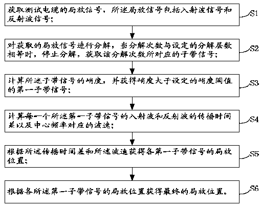
[0060] refer to figure 1 As shown, the present invention provides a method for locating partial discharge of power cables, comprising the following steps:

[0061] S1. Obtain a partial discharge signal of the test cable, where the partial discharge signal includes an incident wave signal and a reflected wave signal.

[0062]Specifically, use the oscillating wave voltage detection method to obtain the partial discharge signal of the test cable, extract a partial discharge signal segment, including an incident wave and a reflected wave signal, denoted as x(n), and the sampling frequency is fs. The oscillatory wave voltage detection method is a common method for cable partial discharge signal detection, and will not be introduced in detail here.

[0063] S2. Decompose the obtained partial discharge si...


PUM


Abstract

The invention provides a power cable partial discharge positioning method. The method comprises the steps that S1 a partial discharge signal of a test cable is acquired, wherein the partial dischargesignal comprises an incident wave signal and a reflected wave signal; S2 the acquired partial discharge signal is decomposed; when the number of times of decomposition is equal to the set number of decomposition layers, the decomposition is stopped; a sub-band signal corresponding to the number of times of decomposition is acquired; S3 the kurtosis of the sub-band signal is calculated, and a firstsub-band signal whose kurtosis is greater than a set kurtosis threshold is acquired; S4 the wavefront position propagation time difference of the incident wave and the reflected wave of each first sub-band signal and the wave velocity corresponding to the center frequency are calculated respectively; S5 according to the propagation time difference and the wave velocity, the partial discharge position of each first sub-band signal is acquired; and S6 the final partial discharge position is acquired according to the partial discharge position of each first sub-band signal. According to the invention, the accuracy of partial discharge positioning can be improved.

Description

technical field [0001] The invention relates to the field of partial discharge positioning, in particular to a method for locating partial discharge of power cables. Background technique [0002] With the continuous growth of the national economy, the urban distribution network has achieved rapid development. Due to its superior electrical and physical properties, power cables have been widely used and become an important part of the urban distribution network and are in a state of rapid growth. According to statistical data, its average annual growth rate reaches 35%. Insulation degradation of power cables will occur during long-term operation, resulting in partial discharge, and partial discharge will accelerate the deterioration of insulation materials, thereby shortening the life of the cable. Timely detection of cable insulation defects and effective measures can avoid defect deterioration and cause failures. Since power cables are laid underground, maintenance is inco...

Claims


Application Information

Patent Timeline
Patent Type & Authority Applications(China)
IPC IPC(8): G01R31/12
CPCG01R31/1272
Inventor 严玉婷李舒适刘顺桂艾精文卢旭
Owner SHENZHEN POWER SUPPLY BUREAU
Why Eureka
Try Eureka