Power Splitter/Combiner

A combiner and shunt technology, which is applied to circuits, waveguide-type devices, connecting devices, etc., can solve the problems of cumbersome development, production and management of power dividers, decreased port isolation, and phase imbalance. Production and promotion and application, improved port isolation, and the same effect of accurate signal phase

Active Publication Date: 2021-06-22
BEIJING XIAOMI MOBILE SOFTWARE CO LTD
View PDF4 Cites 0 Cited by
  • Summary
  • Abstract
  • Description
  • Claims
  • Application Information

AI Technical Summary

Problems solved by technology

[0003] The current power divider is designed due to size defects, radiation coupling, and phase imbalance introduced by surrounding media and metal interference, resulting in a decrease in port isolation (generally 20DB~25DB), requiring repeated debugging and boarding, and a long development cycle.
Moreover, after the design and commissioning of the current power divider are completed, changes in the installation position and shielding structure may cause phase imbalance, resulting in a decrease in port isolation
Therefore, it is necessary to design different power splitters for different installation environments, which makes the development, production and management of power splitters more cumbersome

Method used


Image

  • Power Splitter/Combiner
  • Power Splitter/Combiner
  • Power Splitter/Combiner

Examples


Embodiment Construction

[0047] Reference will now be made in detail to the exemplary embodiments, examples of which are illustrated in the accompanying drawings. When the following description refers to the accompanying drawings, the same numerals in different drawings refer to the same or similar elements unless otherwise indicated. The implementations described in the following exemplary examples do not represent all implementations consistent with the present disclosure. Rather, they are merely examples of apparatuses and methods consistent with aspects of the present disclosure as recited in the appended claims.

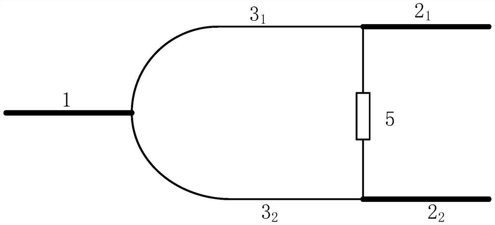
[0048] figure 1 It is an exemplary circuit diagram of a 2-way equally divided microstrip power divider in the related art. Such as figure 1 As shown, in an ideal state: when the even mode is excited, the power input by the common port 1 passes through two completely equal branches 3 1 , branch 3 2 After the phase is the same, there is no voltage difference between the two ends of t...


PUM


Abstract

The present disclosure relates to a power divider / combiner. The power divider / combiner includes: a common port, multiple branch ports, branches corresponding to the multiple branch ports, at least one phase compensation device set in the power divider / combiner according to the preset connection relationship, and at least one isolation resistor. By setting at least one phase compensation device in the power divider / combiner, not only the port isolation and insertion loss performance of the power divider / combiner can be improved, but also the radiation coupling between the split ports can be offset to further improve the port performance. isolation. In addition, the phase imbalance caused by various types of interference can be easily and conveniently compensated by the phase compensation device, which greatly reduces the number of debugging and board casting, and shortens the development cycle. Moreover, the power divider / combiner is applicable to different installation environments, and can ensure high isolation, which is convenient for development and production, and is more conducive to mass production and popularization and application.

Description

technical field [0001] The present disclosure relates to the technical field of communication, and in particular to a power divider / combiner. Background technique [0002] A power divider is a radio frequency device that divides one radio frequency signal into two or more channels, equally or unequally divided, and it can also synthesize multiple radio frequency signals into one signal, which can be called a power combiner at this time. It is widely used in signal distribution and signal combining applications, such as multi-antenna systems, multi-base station systems, multi-channel signal systems, and home cable TV distribution networks. Indexes such as port isolation, insertion loss, and phase balance have an important impact on the performance of the entire power divider. [0003] The current power divider is designed due to size defects, radiation coupling, and phase imbalance introduced by surrounding media and metal interference, resulting in a decrease in port isolat...

Claims


Application Information

Patent Timeline
Patent Type & Authority Patents(China)
IPC IPC(8): H01P5/16
CPCH01P5/16
Inventor 石英官
Owner BEIJING XIAOMI MOBILE SOFTWARE CO LTD
Why Eureka
Try Eureka