Switchgear cabinet

A switchgear and cabinet body technology, which is applied in the field of switchgear, can solve problems such as inconvenient installation on site and difficulties in processing busbar bridge pipes, and achieve the effects of improving construction efficiency, reducing on-site construction, and solving processing difficulties

Active Publication Date: 2019-03-29
HENAN PINGGAO GENERAL ELECTRIC CO LTD +2
View PDF12 Cites 2 Cited by
  • Summary
  • Abstract
  • Description
  • Claims
  • Application Information

AI Technical Summary

Problems solved by technology

[0005] The purpose of the present invention is to provide a switchgear to solve the problems of difficult processing of the busbar bridge pipes and inconvenient installation on site when the existing switchgear enters the line

Method used


Image

  • Switchgear cabinet
  • Switchgear cabinet
  • Switchgear cabinet

Examples


Embodiment Construction

[0027] Embodiments of the present invention will be further described below in conjunction with the accompanying drawings.

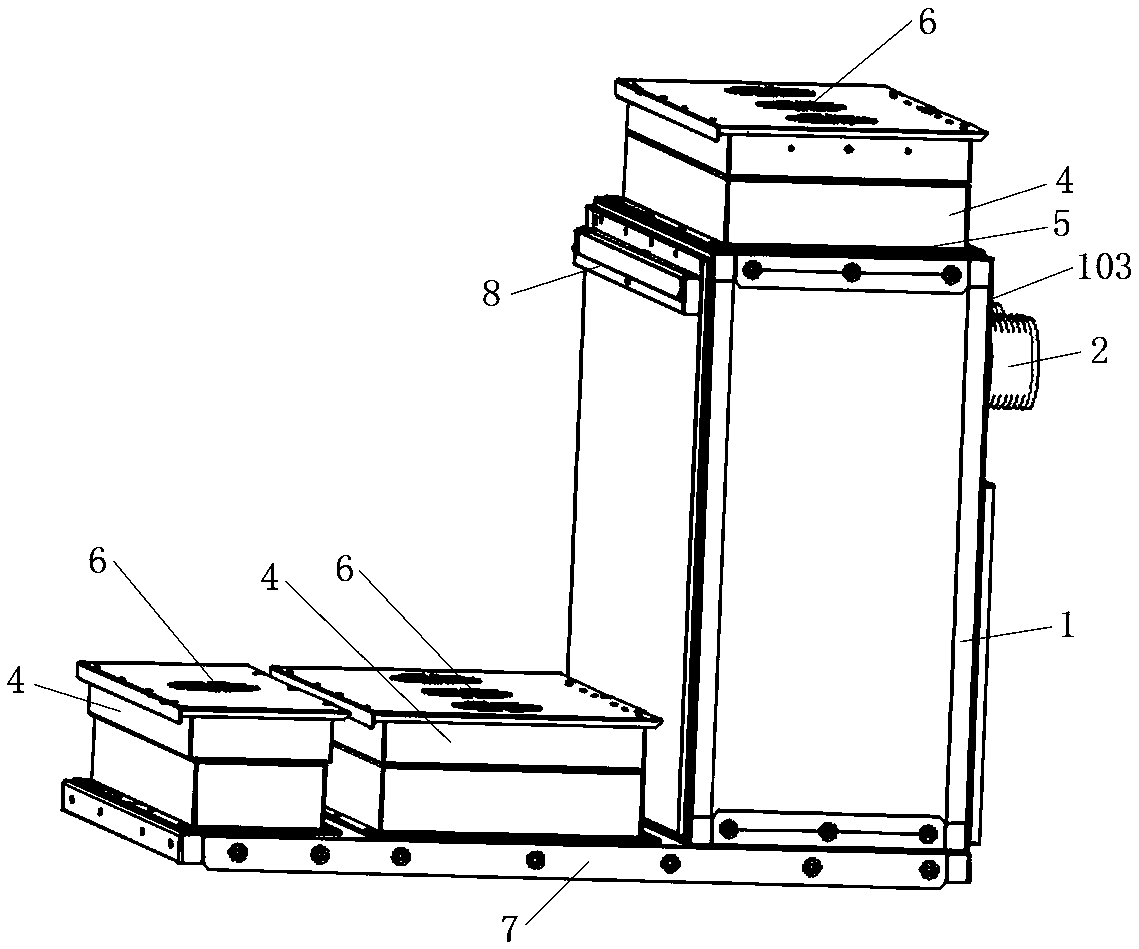
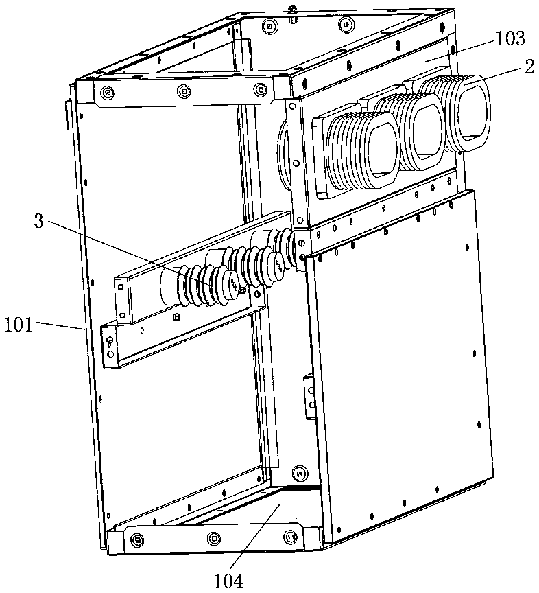
[0028] The specific embodiment of switchgear of the present invention, as Figure 1 to Figure 2 As shown, including the cabinet body, the top of the cabinet body is provided with a busbar bridge seat 1 for the connection of the busbar bridge pipeline. 103 is provided with butt joint wall bushing 2. The bottom of the box structure is provided with a lower sealing plate 104, and the lower sealing plate 104 is provided with a casing for entering the cabinet through the wall (not shown in the figure). The lower sealing plate 104 is provided with a lower pressure relief port for pressure relief of the switchgear, and the top of the box structure is provided with an upper pressure relief port. The lower sealing plate 104 is in closed contact with the top surface of the switch cabinet so that the top surface of the switch cabinet forms a closed contact with t...


PUM


Abstract

The invention relates to a switchgear cabinet which comprises a cabinet body. The top of the cabinet body is provided with a busbar bridge seat to be connected to a busbar bridge pipeline. The busbarbridge seat is a box structure one side of which is provided with a docking area for docking the busbar bridge pipeline. The docking area is provided with a wall bushing for docking. The bottom surface of the busbar bridge seat and the top surface of the cabinet body are provided with communication ports through which the busbar passes, or either the bottom surface of the busbar bridge seat or thetop surface of the cabinet body is provided with an into-cabinet wall bushing to be connected to the busbar. Since one side of the busbar bridge seat is provided with the wall bushing for docking. The busbar can be introduced into the switchgear cabinet through the busbar bridge seat. The busbar bridge seat can be prefabricated. The busbar bridge seat can be directly connected with the switchgearcabinet at a construction site. Therefore, the amount of field construction is reduced, the construction efficiency is improved, and the problem in the prior art is solved that the busbar bridge pipeline is difficult to machine and inconvenient to install on the site.

Description

technical field [0001] The invention relates to a switch cabinet. Background technique [0002] There are generally two ways of entering and exiting the switchgear, namely, cable entry and exit and overhead entry and exit. The cable entry and exit scheme can achieve effective pressure relief, but there are still many disadvantages in the overhead entry and exit lines. For example, when an arcing fault occurs, the internal arcing energy cannot be effectively released, resulting in damage to internal equipment and adjacent switchgear, and even personal injury. Safety. [0003] The Chinese utility model patent with the authorized announcement number CN206498130U discloses a pressure relief structure for the overhead incoming line of the switchgear, including the busbar bridge pipe and the busbar bridge installed in the busbar bridge pipe, an open end of the busbar bridge pipe and the top cover of the switchgear The outer surface forms a closed line contact, which is surrounde...

Claims


Application Information

Patent Timeline
Patent Type & Authority Applications(China)
IPC IPC(8): H02B1/20
CPCH02B1/20
Inventor 田凤雷王焕关红伟朱向宇张二勇王春生郭忠贺田红超陈波马琰陈宗昌张跃进
Owner HENAN PINGGAO GENERAL ELECTRIC CO LTD
Why Eureka
Try Eureka