Wall unit used for laminated shear wall and construction method using wall unit

A technology for superimposing shear walls and wall units, applied in the direction of walls, building components, buildings, etc., can solve the problems of connection strength, matching accuracy defects, high construction complexity, long construction period, etc., to reduce the alignment work. The effect of reducing the amount of on-site construction and simple construction

Active Publication Date: 2018-08-10
河北晶达建筑科技股份有限公司
View PDF4 Cites 4 Cited by
  • Summary
  • Abstract
  • Description
  • Claims
  • Application Information

AI Technical Summary

Problems solved by technology

There are mainly two methods for the construction of existing shear walls. One is to form concrete on-site pouring. This method is greatly affected by the site environment during construction, and the construction complexity is relatively high. More manpower is required and the construction period is long. , in order to eliminate the influence of the above factors, another construction method has been developed in the prior art. The shear wall unit modules are manufactured in the factory, and then a plurality of shear wall unit modules are combined and fixed to form an overall shear wall structure , but with this construction method, there will be defects in the connection strength and matching accuracy between the shear wall unit modules. Therefore, the construction method for the shear wall needs to be improved

Method used


Image

  • Wall unit used for laminated shear wall and construction method using wall unit
  • Wall unit used for laminated shear wall and construction method using wall unit
  • Wall unit used for laminated shear wall and construction method using wall unit

Examples


Embodiment Construction

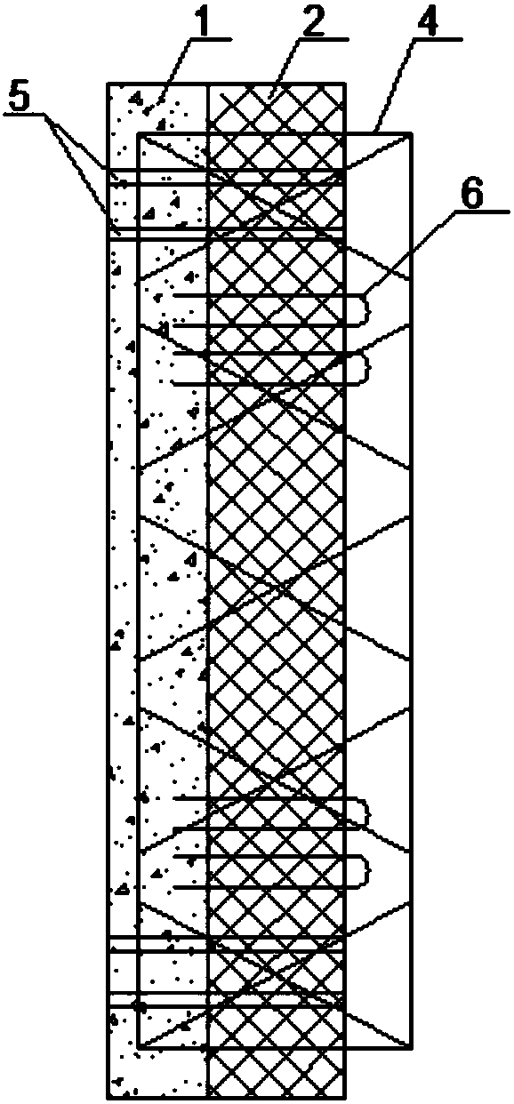
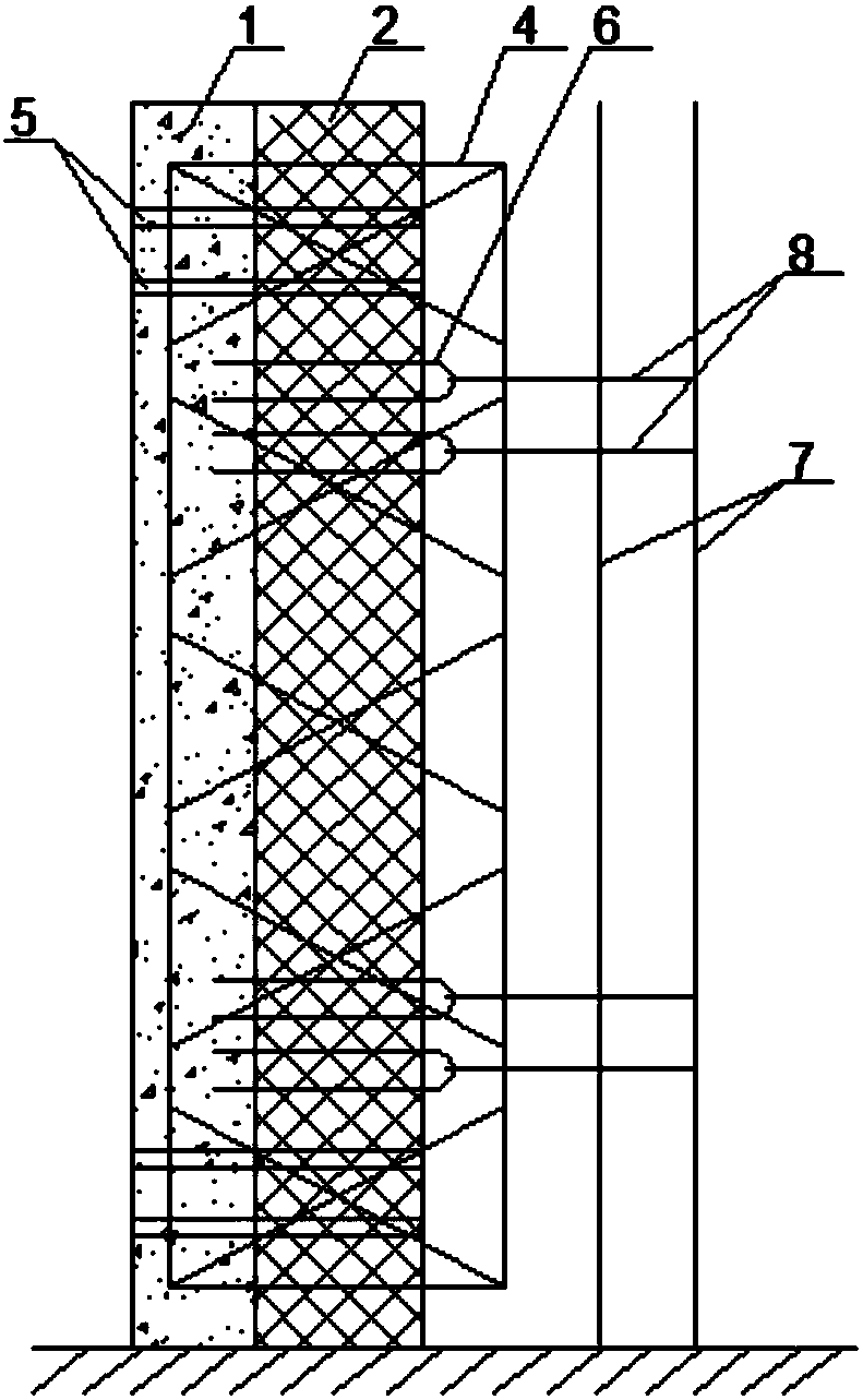
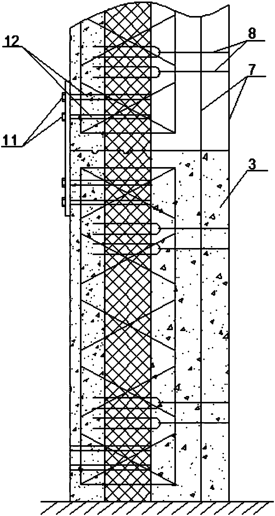
[0022] The present invention relates to a wall unit for a laminated shear wall and a construction method using the same. The wall unit includes a steel wire grid 4 and an insulating layer 2 and a pouring layer filled on the steel wire grid 4. The thermal insulation layer 2 is embedded in the steel wire grid frame 4, the pouring layer is a prefabricated concrete protective layer 1 arranged on one side of the thermal Auxiliary anchors 6 are buried; the wall unit composed of the above structure is prefabricated in the factory, and fixed after being transported to the site, and the inner part of the insulation layer 2 is cast in-situ to form the cast-in-situ concrete layer 3, which is then fixed and poured layer by layer to form a stack Combined with the shear wall structure, the specific process of construction is explained through specific examples.

[0023] Specific examples, such as figure 1 As shown, the steel wire mesh frame 4 is in the form of a truss structure. One end of...


PUM


Abstract

The invention relates to a wall unit used for a laminated shear wall and a construction method using the wall unit. The wall unit comprises a steel wire frame, and an insulating layer and a casting layer filled on the steel wire frame, wherein the insulating layer is embedded into the steel wire frame; the casting layer is a prefabricated concrete protective layer arranged on one side of the insulating layer; mounting fixing holes are formed in the outer end face of the prefabricated concrete protective layer; auxiliary pulling fasteners are preburied inside the prefabricated concrete protective layer, and are mounted layer by layer during construction; vertical load-bearing bars are arranged on the inner side of an insulating board, and are connected with the auxiliary pulling fasteners in virtue of pulling fasteners used for anchoring; a casting template is arranged outside the vertical load-bearing bars, and then casting is performed on a cavity between the insulating layer and thetemplate, to form a cast-in-place concrete layer. The vertically adjacent wall units are fixedly connected through fixed parts and bolts, and then setting and casting operations of the template are carried out, the shear wall constructed by using the construction method can greatly simplify the construction process and also has the strength of an integral casting wall, and the requirement of the shear wall is highly met.

Description

technical field [0001] The invention relates to the field of building technology, in particular to a wall unit for a laminated shear wall and a construction method using the same. Background technique [0002] The shear wall uses reinforced concrete wall panels to replace the beams and columns in the frame structure, which can bear the internal forces caused by various loads and can effectively control the horizontal force of the structure. The shear wall structure is widely used in high-rise buildings. There are mainly two methods for the construction of existing shear walls. One is the formation of concrete poured on site. This method is greatly affected by the site environment during construction, and the construction complexity is relatively high. More manpower is required and the construction period is long. , in order to eliminate the influence of the above factors, another construction method has been developed in the prior art. The shear wall unit modules are manufac...

Claims


Application Information

Patent Timeline
Patent Type & Authority Applications(China)
IPC IPC(8): E04B2/56E04B1/61
CPCE04B1/6116E04B2/56
Inventor 张晶廷
Owner 河北晶达建筑科技股份有限公司
Why Eureka
Try Eureka