Fabricating method of upper and lower self-insulation outer walls and floor slab

An assembly method and self-insulation technology, applied in the directions of insulation, floor, wall, etc., can solve the problems of easy collision and bending of steel bars, long construction time, and high cost of grouting materials, and achieve improved seismic strength, less on-site construction, and no water seepage. hidden effect

Active Publication Date: 2018-11-13
绿建科技集团新型建材高技术有限公司
View PDF4 Cites 4 Cited by
  • Summary
  • Abstract
  • Description
  • Claims
  • Application Information

AI Technical Summary

Problems solved by technology

[0003] In the prior art, the above-mentioned assembly nodes have the following main problems during construction: 1. When the shear wall is hoisted, the steel bars protruding from the bottom are easy to collide and bend, and manual calibration and adjustment are required in the later stage, and the construction efficiency is low; 2. The top of the shear wall The accuracy of the protruding steel bars reserved on the side is difficult to achieve accurately, and the situation of cutting the reserved protruding steel bars during construction often occurs, resulting in waste of steel bar materials and affecting the quality of the project, and it is time-consuming and labor-intensive to accurately align the steel bars and sleeves , it is prone to serious misalignment that leads to the failure of installation, which seriously affects the construction period and construction cost; 3. The grouting quality of sleeve grouting varies, and the grouting density is difficult to uniform and strictly control, and the grouting material density at the grouting anchor connection joint lacks effective detection method, the cost of grouting materials is high, and the cleaning of grouting equipment is time-consuming and complicated; 4. The height of the mortar joints between the shear walls cannot be accurately controlled, and the density and strength are greatly reduced compared with the prefabricated shear wall components. There is a hidden danger of water seepage; 5. The cleaning of grouting equipment is time-consuming and complicated; 6. The quality of the slurry is high and the cost is high; 7. The labor cost is high, the construction time is long, and the construction quality is difficult to control

Method used


Image

  • Fabricating method of upper and lower self-insulation outer walls and floor slab
  • Fabricating method of upper and lower self-insulation outer walls and floor slab
  • Fabricating method of upper and lower self-insulation outer walls and floor slab

Examples


Embodiment 1

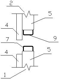
[0073] see figure 1 with figure 2 As shown, the assembly method of the upper and lower self-insulating external walls and the floor in this embodiment includes the first shear wall 1 , the second shear wall 2 and the floor 3 . Both the first shear wall 1 and the second shear wall 2 include an outer thermal insulation layer 4 and an inner load-bearing layer 5 connected as one, and the bottom side of the thermal insulation layer 4 is longer than the load-bearing layer 5, and the top side is lower than the load-bearing layer 5; the load-bearing layer 5 is provided with steel mesh (not drawn among the figure). The top side and the bottom side of the load-bearing layer 5 are provided with prefabricated connecting beams, and connecting steel bars are arranged in the prefabricated connecting beams. In this embodiment, the connecting steel bars are stirrups; The beam 6 is provided with a first stirrup 7; the bottom side of the load-bearing layer 5 of the second shear wall 2 is a se...

Embodiment 2

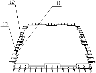
[0080] refer to Figure 5 As shown, the assembly method of the upper and lower self-insulating exterior walls and floors in this embodiment includes the first shear wall 1, the second shear wall 2 and the floor 3, the first shear wall 1 and the second shear wall 2 both include an insulation layer 4 and a load-bearing layer 5; the insulation layer 4 and the load-bearing layer 5 are connected into one body, and the insulation layer 4 is a fiber cement insulation board, the two sides are wider than the load-bearing layer 5, the lower part is longer than the load-bearing layer 5, and the upper part is lower than the load-bearing layer. Layer 5. The load-bearing layer 5 is provided with a double-sided steel mesh (not marked in the figure), and the double-sided steel mesh is formed by cross-connecting longitudinal rectangular steel rings and vertical rectangular steel rings 14 .

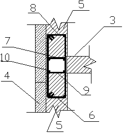
[0081] see Figure 4 The vertical section of the external wall shear wall shows the distribution of v...

Embodiment 3

[0089] Such as Figure 4 , Figure 7 , Figure 8 As shown, the assembly method of the upper and lower self-insulating exterior walls and floors in this embodiment includes the first shear wall 1, the second shear wall 2 and the floor 3, and the structure of the assembly nodes is roughly the same as that in Embodiment 2, specifically The difference is that the positions of the longitudinal steel bars 10 are different, and the specific description is as follows:

[0090] see Figure 7 As shown, in this embodiment, the longitudinal steel bar 10 is arranged inside the rectangular steel bar anchor ring 15 and is close to the surface of the load-bearing layer 5, that is, the rectangular steel bar protruding from the top side of the load-bearing layer 5 of the first shear wall 1 In the anchor ring 15, two first longitudinal steel bars 19 are arranged close to the surface of the load-bearing layer 5, and in the rectangular reinforcement anchor ring 15 protruding from the bottom sid...


PUM


Abstract

The invention provides a fabricating method of upper and lower self-insulation outer walls and a floor slab. The fabricating method comprises the following steps that S1, shear walls and the floor slab are prefabricated; S2, hoisting and installing are carried out, specifically, a first shear wall is hoisted and positioned, the floor slab is hoisted and is arranged at one end of the top side the first shear wall, a second shear wall is hoisted and is arranged on the top side of the first shear wall, the inner face of the bottom side of a heat preservation layer of the second shear wall is tightly attached to the upper wall of a load-bearing layer of the first shear wall, the bottom side of a load-bearing layer of the second shear wall is arranged on the top side of the floor slab, a cavityis formed by the floor slab, the load-bearing layer of the fist shear wall, the load-bearing layer of the second shear wall and the bottom side of the heat preservation layer of the second shear wall, and longitudinal steel bars, tie bars and anchoring parts are ingeniously arranged in different modes; and S3, pouring and connecting are carried out, specifically, concrete is poured in the cavityto form a self-insulation double-overlapping post-pouring connecting beam or a double-anchoring horizontal post-pouring strip, and the floor slab, the first shear wall and the second shear wall are connected into a whole. On-site construction quantity of the fabricated joint is little, the manufacturing cost is low, the construction period is saved, and integrality and anti-shock strength of a building are improved.

Description

technical field [0001] The invention belongs to the technical field of prefabricated buildings, and in particular relates to an assembly method of upper and lower self-insulating exterior walls and floor slabs. Background technique [0002] In the prior art, the main form of the assembly joint between the shear wall and the floor is: the upper and lower shear walls are connected by a grouting sleeve, the laminated floor is placed on the top side of the shear wall, and the laminated floor is poured after placing the longitudinal reinforcement. The cast-in-place layer of the floor slab forms a whole with the laminated floor slab and the shear wall. [0003] In the prior art, the above-mentioned assembly nodes have the following main problems during construction: 1. When the shear wall is hoisted, the steel bars protruding from the bottom are easy to collide and bend, and manual calibration and adjustment are required in the later stage, and the construction efficiency is low; ...

Claims


Application Information

Patent Timeline
Patent Type & Authority Applications(China)
IPC IPC(8): E04B1/04E04B2/68E04B5/21E04B1/76
CPCE04B1/04E04B1/046E04B1/762E04B2/68E04B5/21
Inventor 谢向荣谢怀宇沈鸣李浩谢向阳赵万选
Owner 绿建科技集团新型建材高技术有限公司
Why Eureka
Try Eureka