
Tie device

A technology of limiting device and plate clamp, which is applied in the direction of house structure support, house structure support, and accessories of scaffolding, etc., can solve the problems of troublesome disassembly, unreusable anchor bolt cost, and high cost.

Pending Publication Date: 2020-01-10
SHANGHAI NO 4 CONSTR
View PDF6 Cites 1 Cited by
  • Summary
  • Abstract
  • Description
  • Claims
  • Application Information

AI Technical Summary

Problems solved by technology

The pre-embedded method is only suitable for new structures. Embedded parts, steel pipes, steel bars, etc. are pre-embedded on the outer wall before pouring concrete. The advantages of the pre-embedded method are good rigidity and accurate embedding position, but this method is costly and troublesome to disassemble. , the dismantled hole needs to be sealed in the later stage
The post-anchoring method is applicable to both new and old building structures. The principle is to drill holes on the side of the wall, install expansion anchors or chemical anchors, and then connect them with anchor plates welded together with steel pipes in advance. The advantage is good rigidity. , There is no hole filling process, so there is no hidden danger of water seepage, but this method needs to make holes in the outer wall, destroy the outer wall, and after the construction is completed, the anchor bolts cannot be reused and the cost is high
[0004] The above two methods are suitable for newly-built exterior walls or buildings with low protection requirements for exterior wall finishes, while for existing buildings, especially historical buildings that need to be protected (whose facades have certain value or have a history that requires protection) building), the above two methods are no longer applicable

Method used


Image

  • Tie device
  • Tie device
  • Tie device

Examples


Embodiment Construction

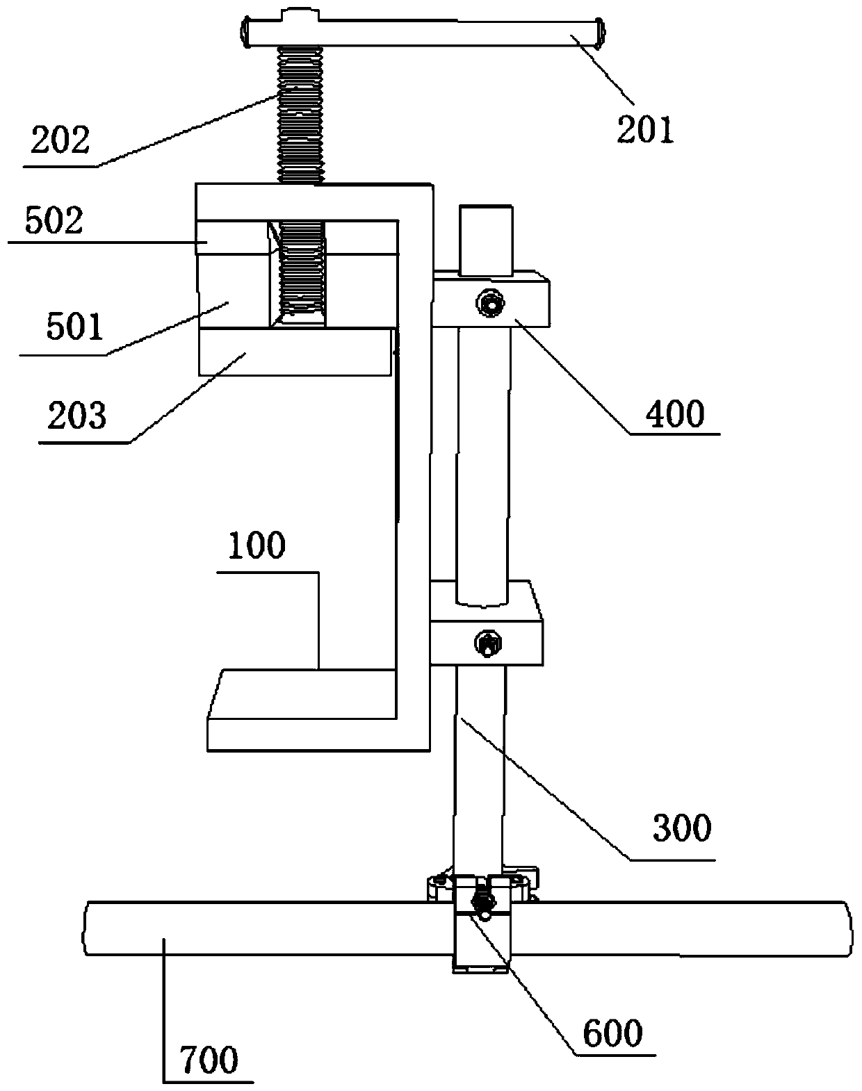
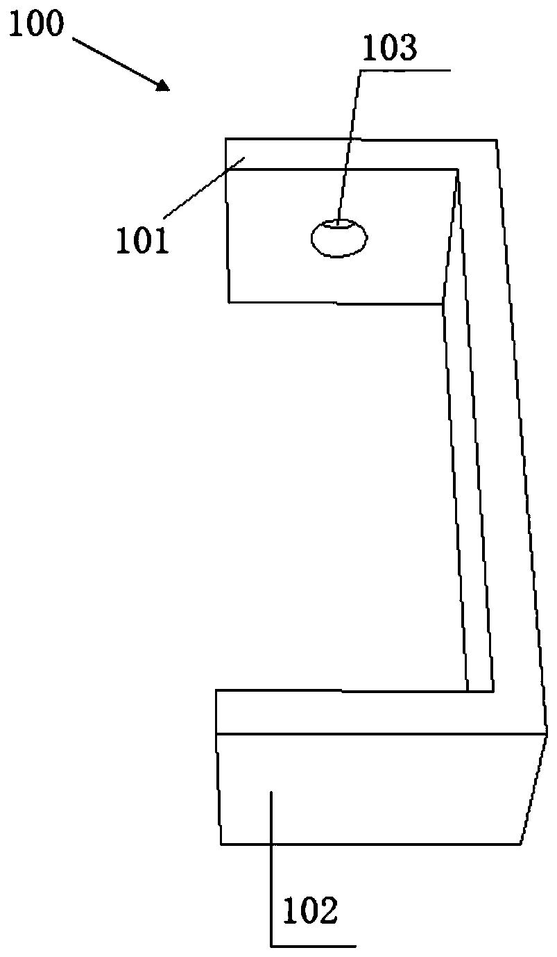
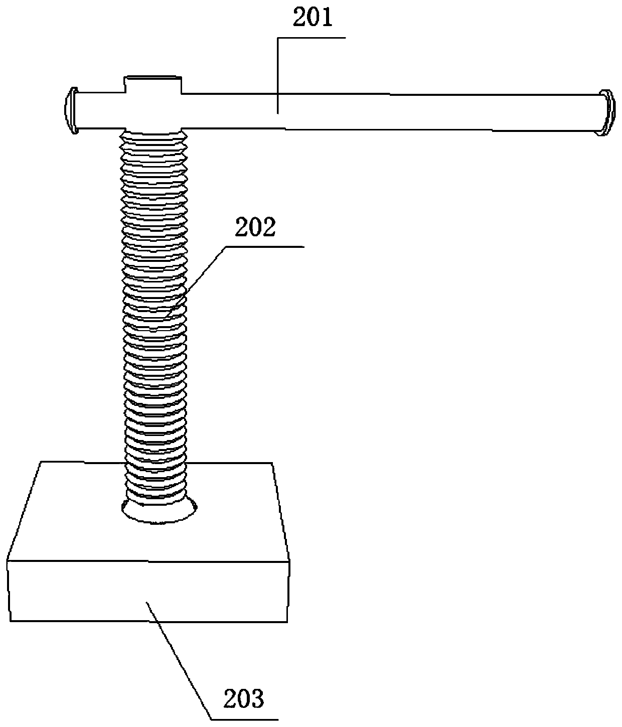
[0030] The following is attached Figure 1~7 The tie-breaking device proposed by the present invention will be further described in detail with the specific embodiments. According to the following description, the advantages and features of the present invention will be clearer. It should be noted that the drawings are in a very simplified form and all use imprecise proportions, which are only used to conveniently and clearly assist in explaining the purpose of the embodiments of the present invention. In order to make the purpose, features and advantages of the present invention more obvious and understandable, please refer to the accompanying drawings. It should be noted that the structure, ratio, size, etc. shown in the accompanying drawings in this specification are only used to match the content disclosed in the specification for the understanding and reading of those familiar with this technology, and are not intended to limit the implementation of the present invention....


PUM


Abstract

The invention discloses a tie device. The tie device comprises a plate clamp, an adjusting clamp and a connector, wherein the plate clamp is detachably connected with the wall of a door / window entrance of an existing building; the adjusting clamp is connected with the plate clamp and is used for adjusting the clamping force between the plate clamp and the wall; and the plate clamp is fixedly connected with a scaffold through a connector. The tie device is suitable for the tying of the scaffolds outside the existing buildings and the outer walls, and is particularly suitable for the existing buildings, the outer walls of which have protection requirements and values; and the wall of the door / window entrance is utilized and is clamped and fixed by adoption of the plate clamp, so that the decoration layer and structural layer of the outer wall are prevented from damage, the rigidity is good, a hole filling process is not required and then no hidden danger such as water seepage is caused.

Description

Technical field [0001] The invention relates to the technical field of building facade construction, in particular to a tie-in device. Background technique [0002] The main function of the scaffold tie device is to connect the scaffold body to the main structure of the building, which can strengthen the overall stability of the scaffold and improve the load-bearing capacity of the scaffold, thereby avoiding major safety accidents such as overturning or collapse of the scaffold. [0003] At present, the commonly used tie-in methods for external walls can be summarized into two types: pre-embedded method and post-anchor method. The pre-embedding method is only suitable for new structures. Before pouring concrete, embed parts, steel pipes, steel bars, etc. in the outer wall. The advantages of the pre-embedding method are good rigidity and accurate burying position, but this method is expensive and troublesome to disassemble , The dismantled hole shall be sealed later. The post-anch...

Claims


Application Information

Patent Timeline
Patent Type & Authority Applications(China)
IPC IPC(8): E04G5/04
CPCE04G5/046
Inventor 蔡观生张铭谷志旺王伟茂陈雪峡何娇孙沈鹏张波任瑛楠张少伟王佳伟
Owner SHANGHAI NO 4 CONSTR
Learn More