Backwashing filter

A filter and backwashing technology, which is applied in the direction of fixed filter elements, filter separation, chemical instruments and methods, etc., can solve the problems of cumbersome cleaning process, affecting work efficiency, affecting filtering effect, etc., and achieves simple and powerful cleaning. Strong, excellent cleaning effect

Inactive Publication Date: 2019-04-02
江苏华卓智能过滤装备系统有限公司
View PDF6 Cites 0 Cited by
  • Summary
  • Abstract
  • Description
  • Claims
  • Application Information

AI Technical Summary

Problems solved by technology

[0002] The filter is to intercept the impurities in the water source to be filtered through the filter to achieve the filtering effect. After the filter has been filtered for a long time, the filtered impurities will gradually attach to the filter to form an impurity layer, which will affect the subsequent Filtration effect, and most of the existing filters are cleaned by disassembling the filter screen, which makes the cleaning process cumbersome and affects work efficiency

Method used


Image

  • Backwashing filter
  • Backwashing filter
  • Backwashing filter

Examples


Embodiment 1

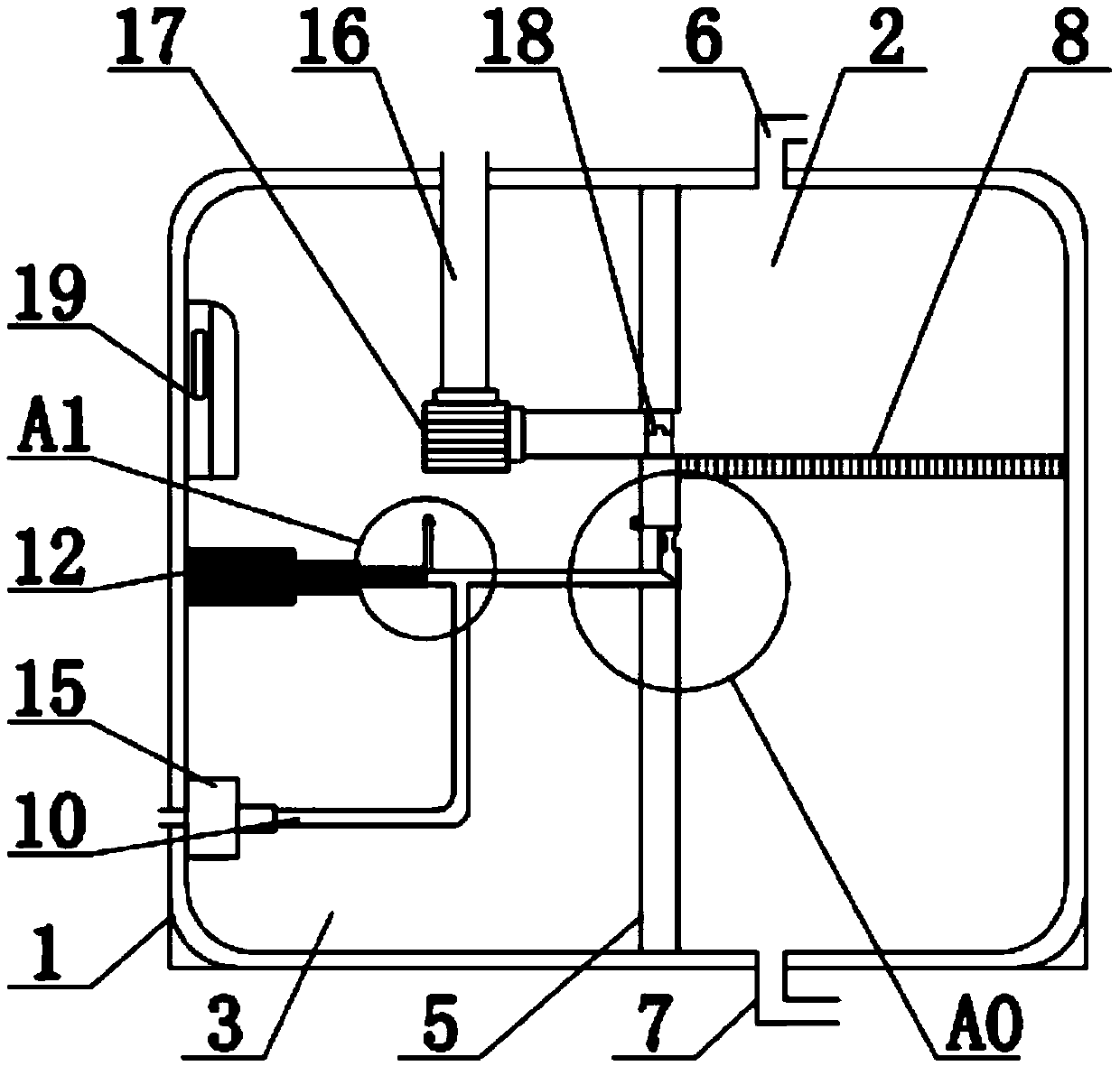
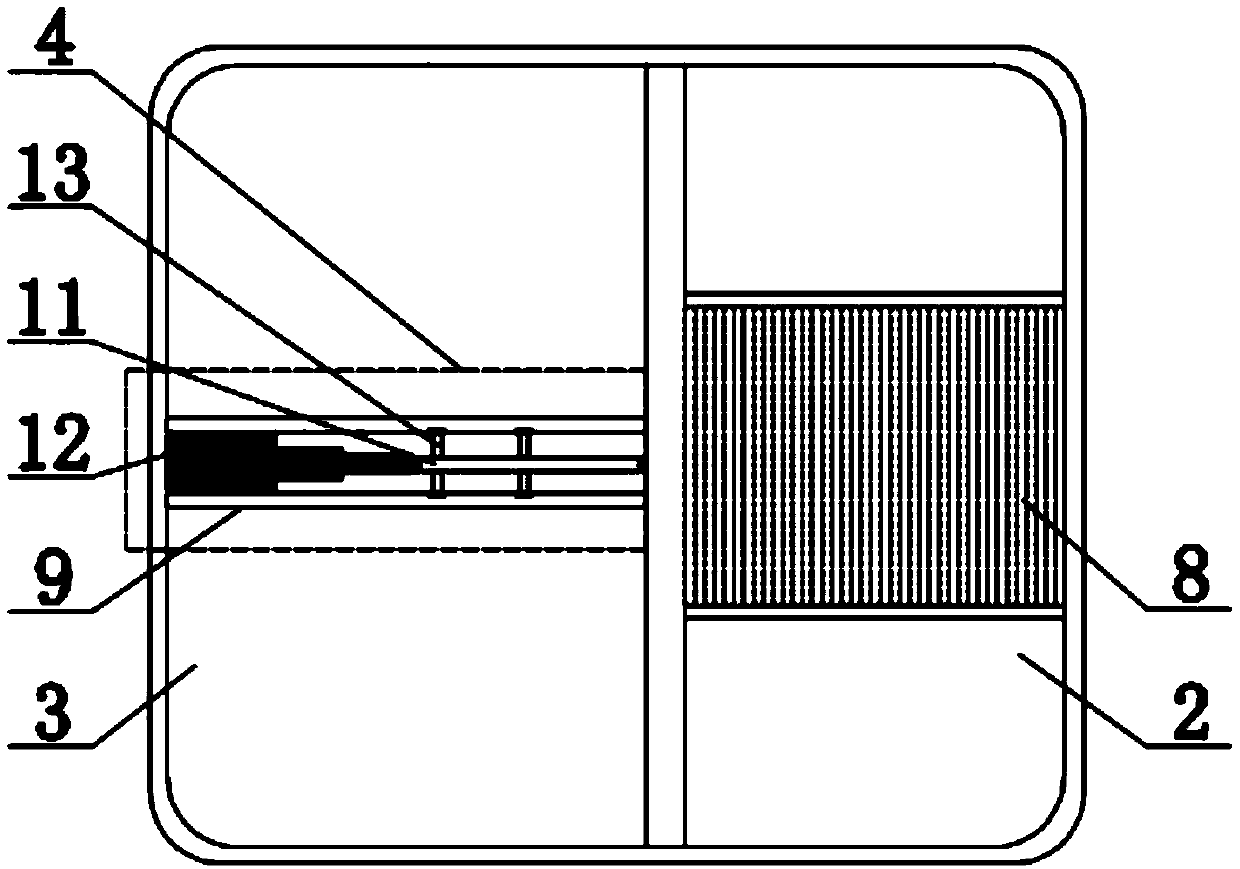
[0024] see figure 1 —4, a backwash filter, including a device housing 1, a filter chamber 2, a flushing chamber 3, and a flushing assembly 4. The interior of the device housing 1 is fixedly connected with a partition 5, and the two sides of the partition 5 are filter The cavity 2 and the flushing cavity 3, the top and the bottom of the filtering cavity 2 are respectively fixedly connected with a water inlet 6 and a water outlet 7, the inside of the filtering cavity 2 is provided with a filter screen 8, and the corresponding two sides of the flushing cavity 3 are The sliding groove 9 is fixedly connected and the two groups of sliding grooves 9 are symmetrical to each other. The sliding groove 9 is located at the lower part of the filter screen 8 relative to the filter screen 8. A flushing assembly 4 is arranged in the sliding groove 9; the flushing assembly 4 includes a flushing pipeline 10 and a flushing head 11. 1. Telescopic rod 12, the inside of the flushing chamber 3 is lo...

Embodiment 2

[0027] see figure 1 -4, the working principle of the present invention is: when in use, the required filtered water flows in through the water inlet 6, and after being filtered by the filter screen 8, it flows out through the water outlet 7;

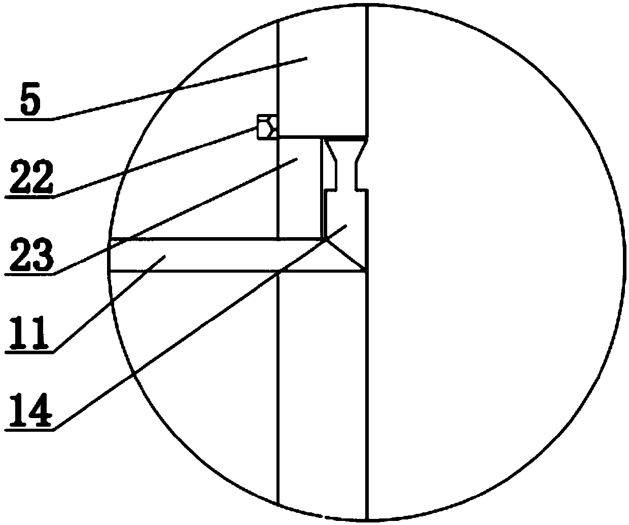
[0028] When the filter screen 8 needs to be cleaned, the PLC controller 19 is controlled by the control button on the console, and the PLC controller 19 can control the telescopic rod 12 so that the telescopic rod 12 stretches out, and the stretched telescopic rod 12 will drive the flushing head connected to it 11. Make the flushing head 11 slide out on the sliding groove 9 through the sliding block 13. When the telescopic rod 12 stretches out until the limit sensor 21 senses the limit block 22, the sensor sends information back to the PLC controller 19 to make it control The telescopic rod 12 is retracted, and the preset PLC control program in the PLC controller 19 will make the telescopic rod 12 reciprocate. Finally, the filter screen...

Embodiment 3

[0030] see figure 1 —4, both sides of the filter cavity 2 can be provided with a flushing cavity 3 and the structure of the installation parts is the same; the upper part of the nozzle 14 is evenly arranged with multiple groups of round holes, and the nozzle 14 can be provided with multiple groups of round holes on the upper part of each group of nozzle 14 The diameters are different; the telescopic rod 12 is provided with a protective housing, and the two sides of the protective housing are fixedly connected with fixed brackets; the lower pressing plate 23 provided at the opening is connected by a hinge, and when the hinge is used, the flushing head 11 passes through the lower part of the lower pressing plate 23 and the area formed between the openings.


PUM


Abstract

The invention discloses a backwashing filter, which comprises a device shell, a filtering chamber, a rinsing chamber and rinsing assemblies, wherein the top portion and the bottom portion of the filtering chamber are respectively connected to a water inlet and a water outlet, a filtering screen is arranged inside the filtering chamber, sliding grooves are arranged inside the rinsing chamber, a stretching rod is connected in the rinsing chamber, one end of the stretching rod is connected to a rinsing head, both sides of the rinsing head are connected to sliding blocks, the other end of the rinsing head is fixedly connected to a spraying nozzle, the rinsing head is connected to a rinsing pipeline, the rinsing pipeline is provided with a micro booster pump, the upper portion, close to the filtering screen, of a separation plate is provided with a sewage discharge port, the sewage discharge port is connected to a sewage discharge pipeline, the sewage discharge pipeline is provided with a micro suction pump, and a PLC controller is arranged inside the rinsing chamber. According to the present invention, the backwashing filter has advantages of reciprocating washing, convenient and quickwashing and strong washing force, and is mainly used for backwashing the filtering screen in the filter.

Description

technical field [0001] The invention relates to the technical field of filter equipment, in particular to a backwash filter. Background technique [0002] The filter is to intercept the impurities in the water source to be filtered through the filter to achieve the filtering effect. After the filter has been filtered for a long time, the filtered impurities will gradually attach to the filter to form an impurity layer, which will affect the subsequent Filtration effect, and most of the existing filters are cleaned after disassembling the filter screen, which makes the cleaning process cumbersome and affects work efficiency. Contents of the invention [0003] In view of the above-mentioned deficiencies in the prior art, the object of the present invention is to provide a backwash filter capable of reciprocating cleaning, convenient and fast cleaning, and strong cleaning force. [0004] The technical solution adopted by the present invention to achieve the above purpose is:...

Claims


Application Information

Patent Timeline
Patent Type & Authority Applications(China)
IPC IPC(8): B01D29/03B01D29/68
CPCB01D29/03B01D29/68
Inventor 孙崇善
Owner 江苏华卓智能过滤装备系统有限公司
Why Eureka
Try Eureka