Eureka AIR delivers breakthrough ideas for toughest innovation challenges, trusted by R&D personnel around the world.

A bidirectional pressing device with multi-point pressing

A pressing device, multi-point technology, applied in positioning devices, auxiliary devices, manufacturing tools, etc., to achieve the effects of convenient operation, improved work efficiency, and improved accuracy

Active Publication Date: 2020-08-14
SHENZHEN LAUN CLEAN TECH CO LTD
View PDF5 Cites 0 Cited by
  • Summary
  • Abstract
  • Description
  • Claims
  • Application Information

AI Technical Summary

Problems solved by technology

[0003] In view of the above problems, the present invention provides a two-way pressing device with multi-point pressing. By setting a plurality of push rods on the first pressing block, the multi-point pressing of the workpiece is realized. The thrust is applied by the rod, which ensures that the thrust of each push rod has a certain degree of independence. A second compression block is provided in the direction perpendicular to the first compression block, which realizes the compression of the workpiece in two directions. By providing the first gear, the push rod gear and the second gear, the pressing function in two directions can be completed only by applying thrust in one direction. The first gear, the push rod gear and the second gear Friction plates are installed between the two gears. When the gears are not synchronized, the gears can continue to rotate, which not only ensures the continuity of the thrust, but also improves the stability and precision of the pressing device. This structure not only realizes The multi-point compression of the workpiece in two directions also solves the problem of workpiece tilting caused by uneven force during compression, and is easy to operate, only need to apply thrust in one direction to complete the above Function, and simple structure, high work efficiency

Method used


Image

  • A bidirectional pressing device with multi-point pressing
  • A bidirectional pressing device with multi-point pressing
  • A bidirectional pressing device with multi-point pressing

Examples


Embodiment

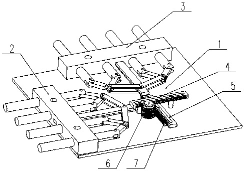
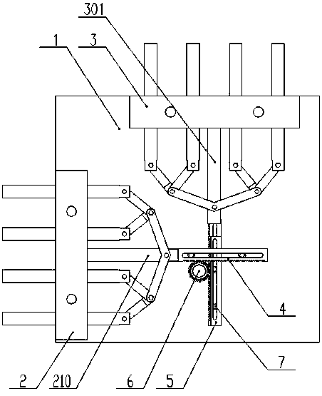
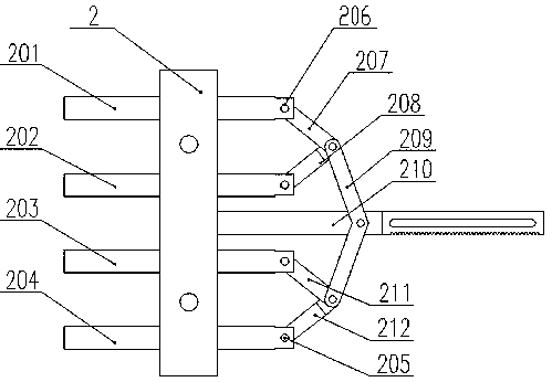
[0028] Such as figure 1 , figure 2 , image 3 , Figure 4 , Figure 5 , Figure 6 , Figure 7 , Figure 8 , Figure 9 as well as Figure 10As shown, a bidirectional pressing device with multi-point pressing includes a bottom plate 1, a first pressing block 2, a first push rod 201, a second push rod 202, a third push rod 203, and a fourth push rod 204 , rotating shaft 205, through hole 206, first connecting rod 207, second connecting rod 208, connecting rod 209, first positioning rod 210, third connecting rod 211, fourth connecting rod 212, positioning hole 213, flat potential hole 214. The second pressing block 3, the second positioning rod 301, the first rack 4, the first U-shaped groove 401, the first straight tooth 402, the first limiting column 403, the supporting column 404, the push rod 5, the first Three U-shaped slots 501, third straight teeth 502, gear shaft 6, plane thrust bearing 601, first gear 602, push rod gear 603, second gear 604, friction plate 605, ...


PUM


Abstract

The invention provides a bidirectional pressing device with a multi-point pressing function. The bidirectional pressing device comprises a bottom plate, a first pressing block, a first push rod, a second push rod, a third push rod, a fourth push rod, a rotating shaft, a through hole, a first connecting rod, a second connecting rod, a connecting rod, a first positioning rod, a third connecting rod,a fourth connecting rod, a positioning hole, a flat potential hole, a second pressing block, a second positioning rod, a first rack, a first U-shaped groove, a first straight tooth, a first limit column, a support column, a push rod, a third U-shaped groove, a third straight tooth, a gear shaft, a plane thrust bearing, a first gear, a push rod gear, a second gear, a friction plate, a second rack,a second U-shaped groove, a second straight tooth and a second limit post. Through the arrangement of structures such as friction sheets, the first gear and the second gear can be driven to rotate, when the gears are not synchronized, the gears can continue to rotate, the continuity of the thrust is ensured, the stability and accuracy of compaction are improved, and operation is convenient.

Description

technical field [0001] The invention relates to the technical field of compression and fixing devices for welding, in particular to a bidirectional compression device with multi-point compression. Background technique [0002] It is usually necessary to position and compress the workpiece during welding, so as to ensure that the welded product can meet the technical requirements. In the actual production process, quick clamps or pliers are usually used to quickly compress and position the workpiece. The pliers can only compress one point. During use, the work efficiency is low, and the workpiece is prone to warping when pressing, which affects the welding effect. Contents of the invention [0003] In view of the above problems, the present invention provides a two-way pressing device with multi-point pressing. By setting a plurality of push rods on the first pressing block, the multi-point pressing of the workpiece is realized. The thrust is applied by the rod, which ensu...

Claims


Application Information

Patent Timeline
Patent Type & Authority Patents(China)
IPC IPC(8): B23Q3/06B23K37/04
CPCB23K37/04
Inventor 张增良
Owner SHENZHEN LAUN CLEAN TECH CO LTD
Why Eureka
Eureka Blog
Learn More