Rod connection structure in multi-section activities

A connection structure and center rod technology, which is applied in the direction of manufacturing tools, material forming presses, presses, etc., can solve problems such as inability to borrow, large concentricity error, and middle rod breakage, so as to prevent hold-off and eliminate Effect of concentricity error

Active Publication Date: 2021-01-12
BO LUO HE SHI MOLD MFG CO
View PDF7 Cites 0 Cited by
  • Summary
  • Abstract
  • Description
  • Claims
  • Application Information

AI Technical Summary

Problems solved by technology

[0002] At present, when the existing powder compacting machine presses the product, there is a concentricity error in the upper and lower mold bases of the powder compacting machine. Before the powder compacting machine compacts the product, the concentricity error needs to be minimized. In the process of use, the position cannot be borrowed, the concentricity error is large, and the middle rod is often broken, resulting in product pressing failure, increased production costs, and reduced production efficiency.
Moreover, the existing middle stick cannot be shaken, which may easily cause the middle stick to break when used

Method used


Image

  • Rod connection structure in multi-section activities
  • Rod connection structure in multi-section activities
  • Rod connection structure in multi-section activities

Examples


Embodiment Construction

[0022] In order to make the object, technical solution and technical effect of the present invention clearer, the present invention will be further described below in conjunction with specific embodiments. It should be understood that the specific embodiments described here are only used to explain the present invention, not to limit the present invention.

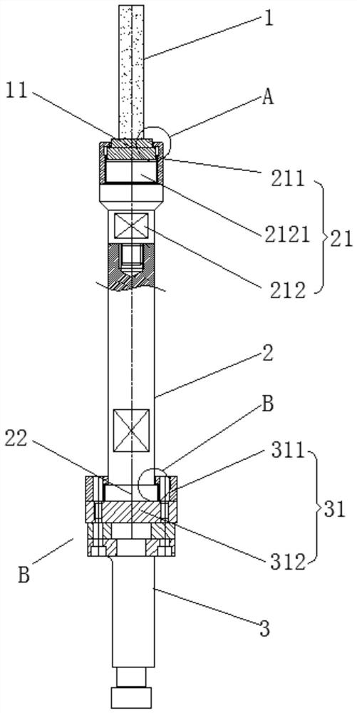
[0023] refer to figure 1 , a multi-section movable middle rod connection structure, including a middle rod 1 connected to each other, a first middle rod connecting rod 2 and a second middle rod connecting rod 3 from top to bottom, the bottom end of the middle rod 1 is provided with a middle rod Base 11, the top of the first middle rod connecting rod 2 is provided with a first connecting structure 21, the middle rod base 11 is movably arranged in the first connecting structure 21, the first middle rod connecting rod 2 A connecting rod base 22 is provided at the bottom end, and a second connecting structure 31 is provided a...


PUM


Abstract

The invention provides a multi-section movable medium rod connecting structure. The multi-section movable medium rod connecting structure comprises a medium rod, a first medium rod connecting bar anda second medium rod connecting bar from top to bottom, wherein the medium rod, the first medium rod connecting bar and the second medium rod connecting bar are connected with each other; the bottom end of the medium rod is provided with a medium rod base; the top end of the first medium rod connecting bar is provided with a first connecting structure; the medium rod base is movably arranged in thefirst connecting structure; the bottom end of the first medium rod connecting bar is provided with a connecting bar base; the top end of the second medium rod connecting bar is provided with a secondconnecting structure; and the connecting bar base is movably arranged in the second connecting structure. According to the multi-section movable medium rod connecting structure provided by the invention, by employing a structure of multi-section movable connection, the concentricity error of the medium rod and a die frame is eliminated, the medium rod is prevented from being broken by restraint,and the vertical concentricity error of the die frame meets the use requirement.

Description

technical field [0001] The invention relates to the technical field of powder compression molding, in particular to a multi-section movable middle rod connection structure. Background technique [0002] At present, when the existing powder compacting machine presses the product, there is a concentricity error in the upper and lower mold bases of the powder compacting machine. Before the powder compacting machine compacts the product, the concentricity error needs to be minimized. During use, it cannot be borrowed, and the concentricity error is large, and the middle rod is often broken, resulting in product pressing failure, increased production costs, and reduced production efficiency. Moreover, the existing middle stick cannot be shaken, which may easily cause the middle stick to be broken during use. Contents of the invention [0003] In order to solve the above technical problems, the present invention provides a multi-section movable middle rod connection structure, ...

Claims


Application Information

Patent Timeline
Patent Type & Authority Patents(China)
IPC IPC(8): B30B11/00B30B15/02
CPCB30B11/00B30B15/026
Inventor 何考贤廖新添
Owner BO LUO HE SHI MOLD MFG CO
Why Eureka
Try Eureka