
Electromagnetic device, supporting assembly and photographic equipment

A technology of electromagnetic devices and supporting components, which is applied in the direction of electromechanical devices, electric components, electrical components, etc., can solve the problems of restricting the rotation of rotating parts, and achieve the effects of avoiding excessive winding, improving the range of rotation, and enhancing application performance

Pending Publication Date: 2019-04-02
FANTASY DYNAMICS SHANGHAI CULTURE COMM CO LTD
View PDF0 Cites 0 Cited by
  • Summary
  • Abstract
  • Description
  • Claims
  • Application Information

AI Technical Summary

Problems solved by technology

However, the rotation range of the above two rotating parts is determined by the rotation range limited by the stopper structure, which may limit the rotation needs of the rotating parts in some cases.

Method used


Image

  • Electromagnetic device, supporting assembly and photographic equipment
  • Electromagnetic device, supporting assembly and photographic equipment
  • Electromagnetic device, supporting assembly and photographic equipment

Examples


Embodiment Construction

[0035] The present invention is described in detail below in conjunction with accompanying drawing:

[0036] Unless otherwise specified, the same reference numerals appearing in the present invention represent the same or similar structures, elements and the like. In order to facilitate clarity of expression, similar symbols appearing in the present invention express the same, similar structures, elements or different structures, parts, etc. the corresponding end wall.

[0037] In order to facilitate the description of the relative positional relationship between the various parts and structures in conjunction with the accompanying drawings and embodiments, if there is no special description, words such as "upper, lower", "top, bottom", "left, right" that appear in the present invention ", "front, back", "one, another" etc. are relative concepts. As an implementation, "upper, lower", "top, bottom", "axial", "vertical direction", "depth direction" can refer to Figure 9 in t...


PUM


Abstract

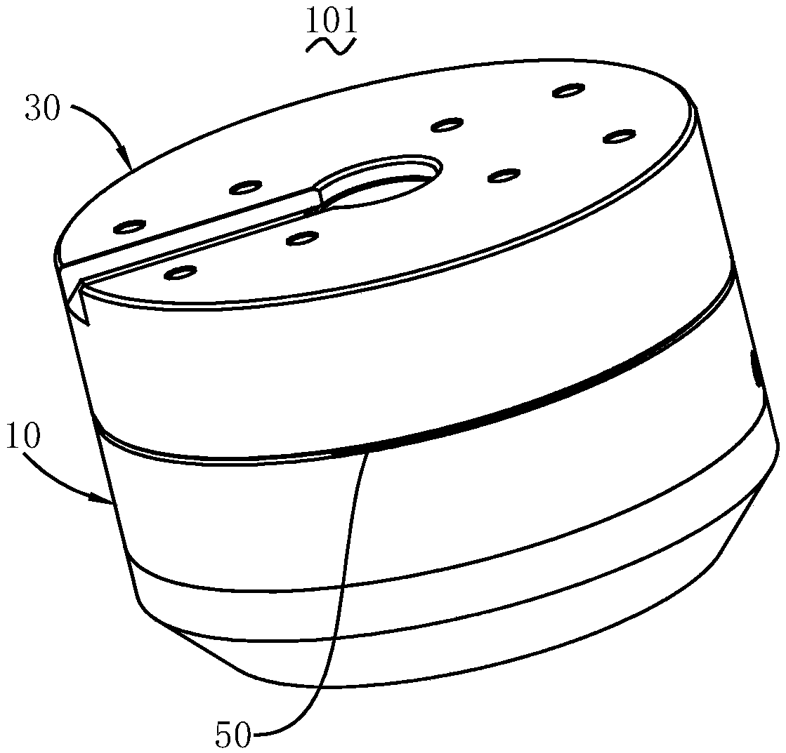
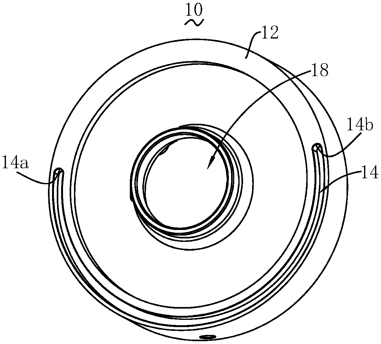
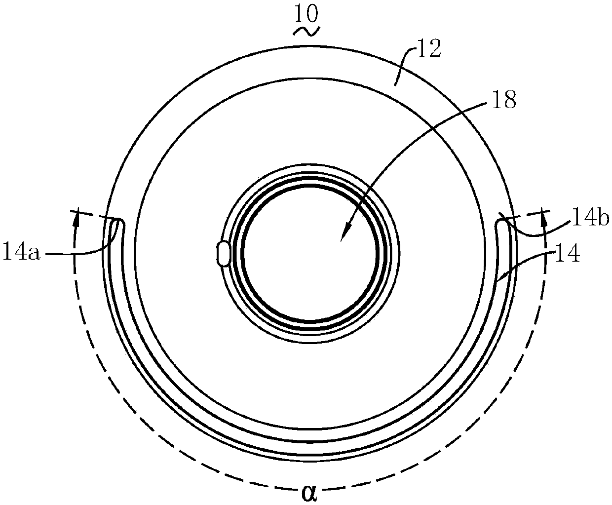
The invention discloses an electromagnetic device, a supporting assembly and photographic equipment. The electromagnetic device comprises a stator, a rotor and a limiting piece. The stator is providedwith a limiting groove. The limiting groove forms two end walls on the stator. The rotor is provided with a matching groove. The matching groove forms two end walls on the rotor. The rotor is rotatably arranged relative to the stator. One end of the limiting piece accommodates in the limiting groove, and is matched with the two end walls of the stator in a resisting mode. The other end of the limiting piece extends into the matching groove, and can be matched with two end walls of a matching seat in a resisting mode. The limiting piece is movably arranged relative to the limiting groove and / or the matching groove. The electromagnetic device further obtains a larger rotational range on a premise of having a limiting function.

Description

technical field [0001] The invention relates to an electromagnetic device, a supporting component and a photographic equipment. Background technique [0002] According to different application requirements, it is often required that the two components can rotate relative to each other. Generally speaking, in some cases, there is no limit to the angle (or number of turns) of one part relative to the other part, and it can freely rotate clockwise and counterclockwise. In other cases, it is necessary to limit the angular range of rotation, and correspondingly, a corresponding stopper structure needs to be provided on one component, so as to prevent the other component from continuing to rotate when the relative rotation of the other component reaches an angle, thereby achieving A requirement to limit the range of rotation of another component. However, the rotation range of the above two rotating parts is determined by the rotation range limited by the stopper structure, whic...

Claims


Application Information

Patent Timeline
Patent Type & Authority Applications(China)
IPC IPC(8): F16M11/06H02K1/12H02K1/22H02K7/00
CPCH02K1/12H02K1/22H02K7/00F16M11/06
Inventor 邱晓华
Owner FANTASY DYNAMICS SHANGHAI CULTURE COMM CO LTD
Learn More