Rotating bracket for infrared telescope

A technology for infrared telescopes and rotating brackets, applied in telescopes, optics, instruments, etc., can solve problems such as inconvenient installation, large volume, and time-consuming, and achieve the effects of preventing excessive inclination angles, reasonable design, and ensuring stability

Inactive Publication Date: 2019-04-02
ZHENGZHOU HAIWEI OPTOELECTRONICS TECH CO LTD
View PDF9 Cites 2 Cited by
  • Summary
  • Abstract
  • Description
  • Claims
  • Application Information

AI Technical Summary

Problems solved by technology

[0003] At present, the telescope bracket is only suitable for application on the horizontal support surface. First, if the user wants to change the observation angle of the infrared telescope during the observation process, the infrared telescope and the bracket must be moved as a whole, while the existing infrared telescope bracket There is no rotating bracket that can automatically adjust the horizontal angle and vertical angle, so it is extremely inconvenient to adjust the observation angle of the infrared telescope. Second, the bracket of the infrared telescope is heavy and inconvenient to carry, and the volume is large, so it is inconvenient to fold and carry. It is very time-consuming to install the infrared telescope for the first time, and it is not easy to install

Method used


Image

  • Rotating bracket for infrared telescope
  • Rotating bracket for infrared telescope
  • Rotating bracket for infrared telescope

Examples


Embodiment Construction

[0018] The following will clearly and completely describe the technical solutions in the embodiments of the present invention with reference to the accompanying drawings in the embodiments of the present invention. Obviously, the described embodiments are only some, not all, embodiments of the present invention. Based on the embodiments of the present invention, all other embodiments obtained by persons of ordinary skill in the art without making creative efforts belong to the protection scope of the present invention.

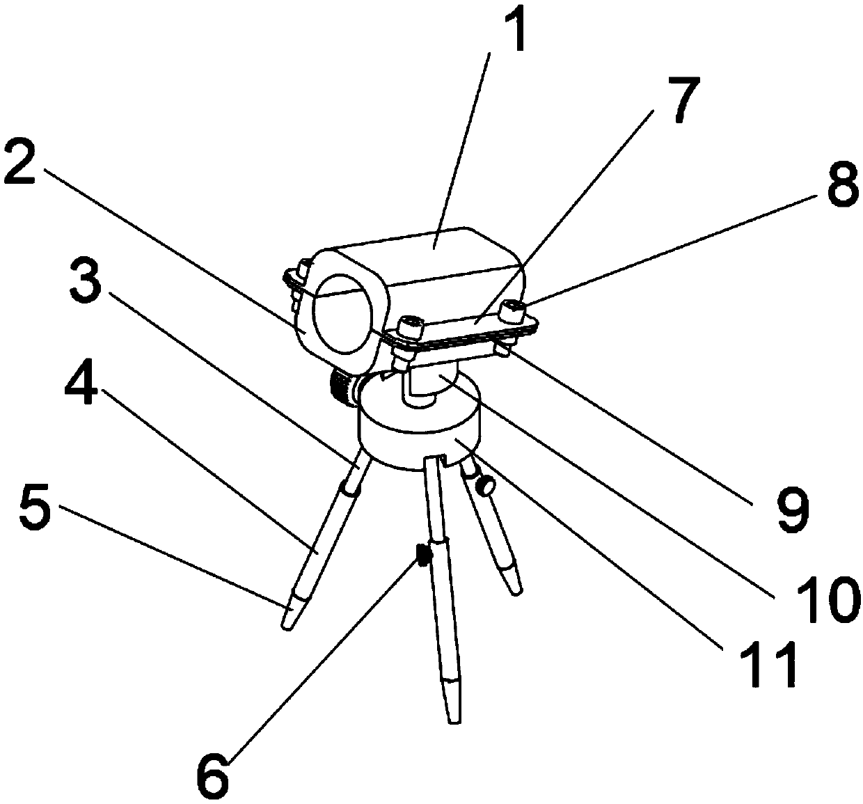
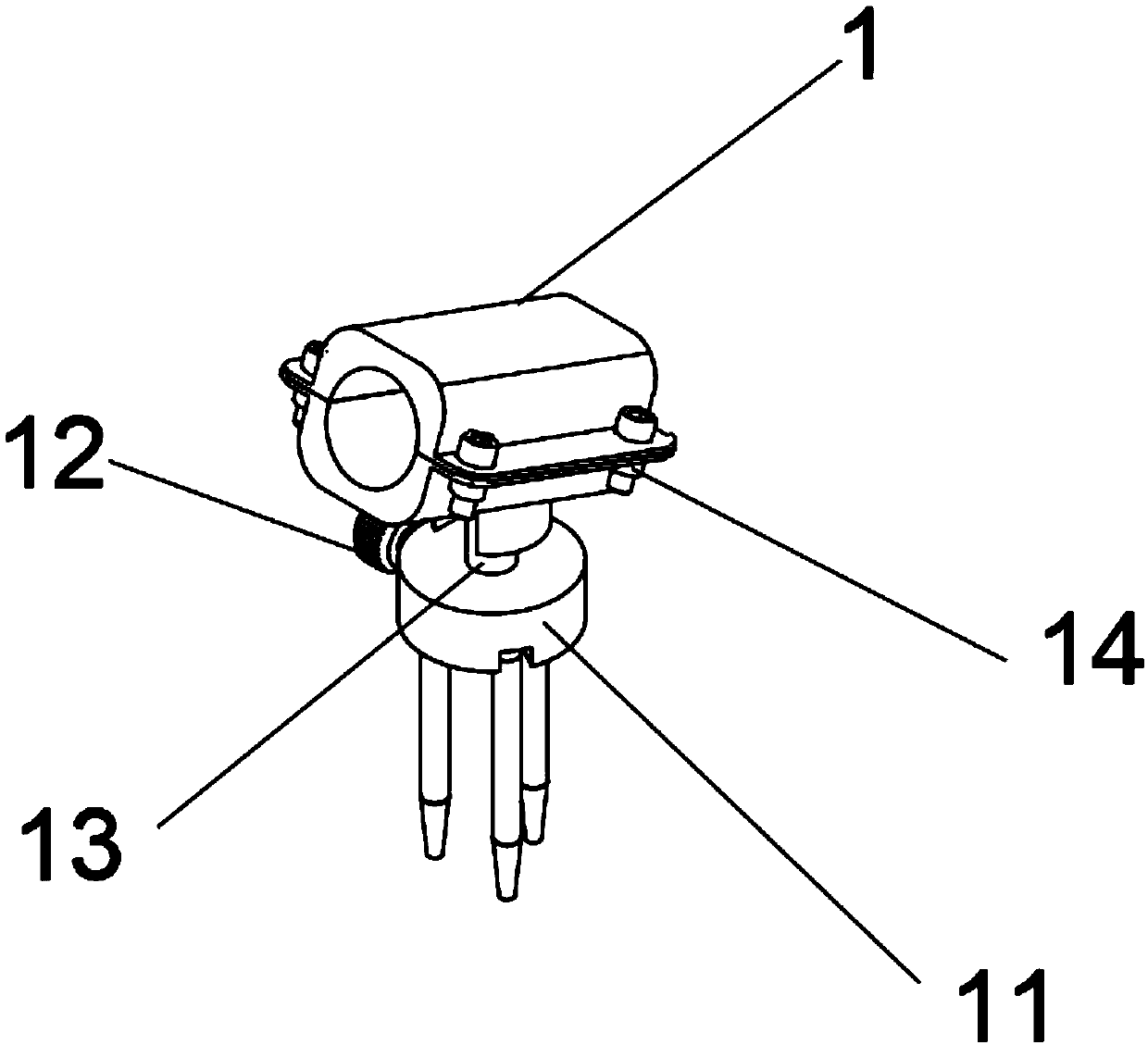
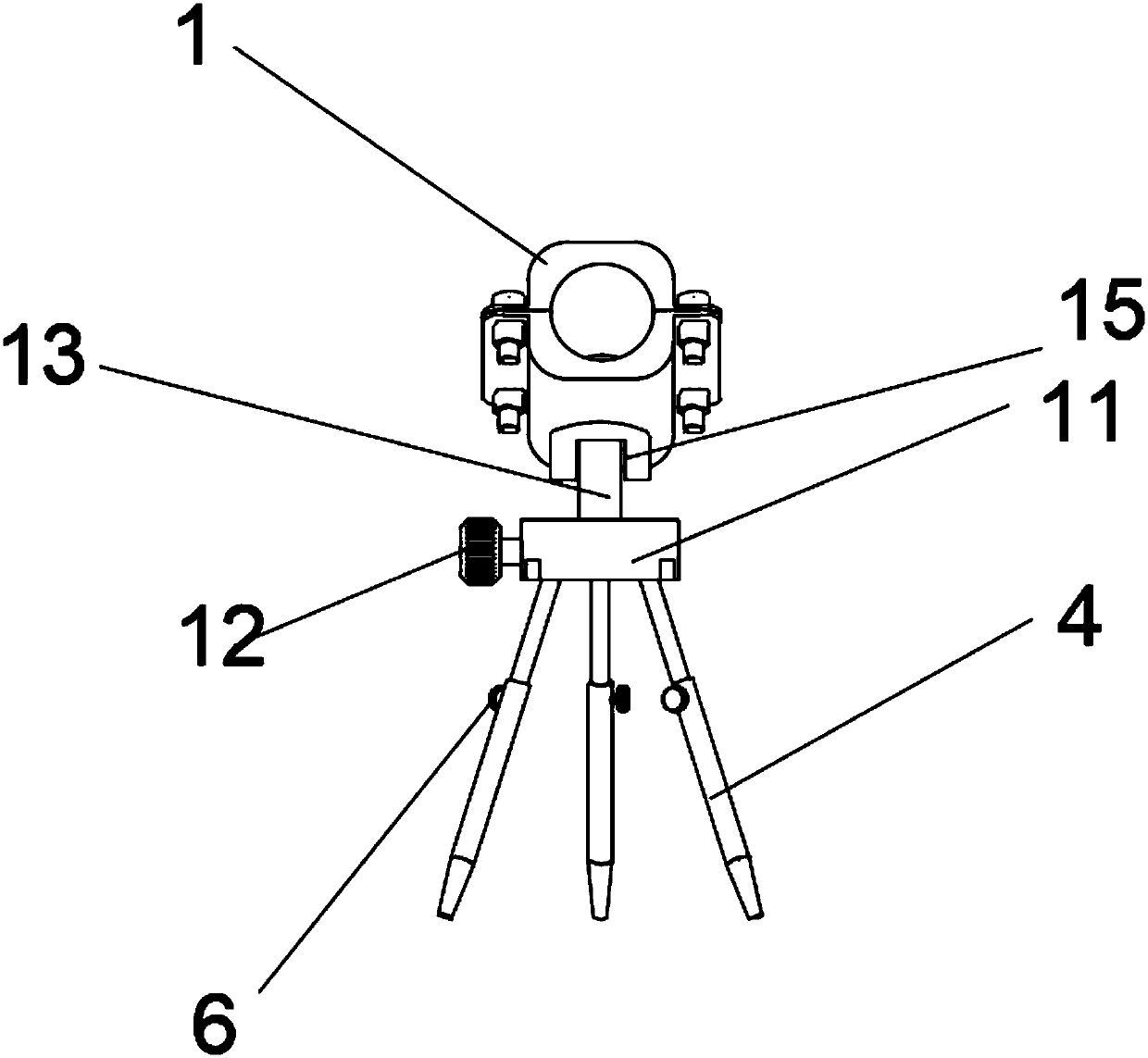
[0019] see Figure 1~4 , a rotating bracket for infrared telescopes, including an upper fixing groove 1, a lower fixing groove 2, telescopic legs 3, a sleeve 4, a foot 5, a fastening knob 6, an upper fixing plate 7, a fixing screw 8, and a lower fixing plate 9. Support 10, mounting plate 11, fine-tuning knob 12, support column 13, nut 14 and rotating shaft 15; the upper fixing groove 1 and the lower fixing groove 2 are installed symmetrically, and the bottom e...


PUM


Abstract

The invention discloses a rotating bracket for an infrared telescope. The rotating bracket comprises an upper fixing groove, a lower fixing groove, telescopic legs, sleeves, support legs, fastening knobs, an upper fixing plate, fixing screws, a lower fixing plate, a support base, a mounting disc, a fine adjustment knob, a support column, nuts and a rotating shaft. The rotating bracket for the infrared telescope has the beneficial effects that the rotating bracket for the infrared telescope is reasonable in design; rubber sleeves are mounted outside the support legs; each of the rubber sleevesis provided with an anti-slip bump; since the rotating bracket is used outdoors, the anti-slip rubber sleeves can play the anti-slip effect to guarantee the stability of the rotating bracket; the upper fixing groove and the lower fixing groove are cooperatively fixed by the fixing screws and the nuts and are detachably connected; through the detachable connection of the fixing screws and the nuts,the infrared telescope mounted on the rotating bracket can be better mounted and dismounted; and the top of the support column is mounted in a support base mounting groove and is rotatably connectedto the support base through the rotating shaft so as to conveniently adjust the vertical angle of the infrared telescope.

Description

technical field [0001] The invention relates to a rotating bracket, in particular to a rotating bracket for an infrared telescope, and belongs to the technical field of optical devices. Background technique [0002] In the existing telescope system, a refracting starfinder with low magnification and wide field of view is often attached next to the infrared telescope, so that the observer can quickly collect the objects to be observed. During this process, the starfinder should always be kept The mirror is parallel to the optical axis of the infrared telescope. To achieve this goal, the industry generally adopts a solution of fixing the infrared telescope and the star finder on a fixed bracket in such a way that the optical axes are parallel to each other. [0003] At present, the telescope bracket is only suitable for application on the horizontal support surface. First, if the user wants to change the observation angle of the infrared telescope during the observation proces...

Claims


Application Information

Patent Timeline
Patent Type & Authority Applications(China)
IPC IPC(8): G02B23/16
CPCG02B23/16
Inventor 焦战威焦子萱陈娇彤
Owner ZHENGZHOU HAIWEI OPTOELECTRONICS TECH CO LTD
Why Eureka
Try Eureka