Pulverizer

A pulverizer and rack technology, used in wood processing appliances, grain processing, manufacturing tools, etc., can solve the problems of accidental interruption of pulverization, large differences in the shape of waste, and many crude fibers of waste, etc. Convenience of materials and the effect of increasing production

Pending Publication Date: 2019-12-03
江苏保龙机电制造有限公司
View PDF0 Cites 0 Cited by
  • Summary
  • Abstract
  • Description
  • Claims
  • Application Information

AI Technical Summary

Problems solved by technology

However, the existing equipment cannot achieve safe and efficient crushing
The main reason: the shape of the waste is very different, and there are many coarse fibers in the waste, which makes the irregular waste easy to be interrupted unexpectedly when crushing, and the crushing effect is poor

Method used


Image

  • Pulverizer
  • Pulverizer
  • Pulverizer

Examples


Embodiment 1

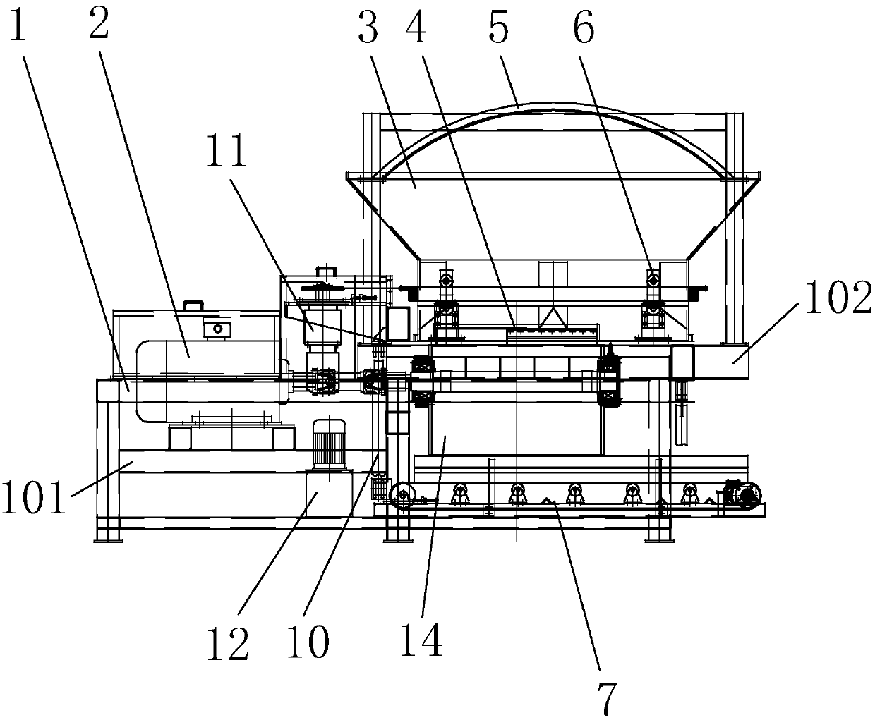
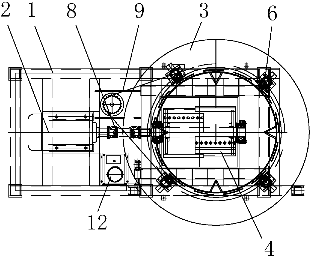
[0037] like Figures 1 to 3 As shown, a pulverizer includes a frame 1, a main deceleration motor 2, a feeding assembly 3, a knife roller assembly 4 and a deceleration auxiliary motor 11, wherein:

[0038] The aforementioned deceleration main motor 2 and deceleration auxiliary motor 11 are both installed on the frame 1;

[0039] The aforementioned deceleration main motor 2 drives the cutter roller assembly 4 to rotate through the coupling 8;

[0040] The aforementioned feeding assembly 3 is located above the knife roller assembly 4;

[0041] The aforementioned feeding assembly 3 includes a conical cylinder 301, a cylinder 302 and a feeding plate 303; the aforementioned conical cylinder 301 is fixed above the cylinder 302, and the inner side of the aforementioned cylinder 302 is fixedly connected to the feeding guide plate 303; the aforementioned conical cylinder 301 The cover 5 can be installed as required;

[0042] The aforementioned deceleration auxiliary motor 11 drives t...

Embodiment 2

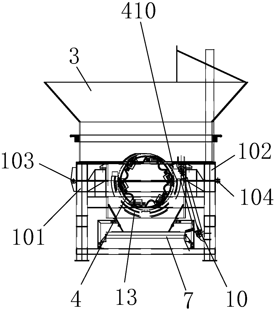
[0049] As an improvement of the first embodiment of the present invention, as Figures 1 to 3 and 12, the aforementioned rack 1 is composed of a lower rack 101 and an upper rack 102, wherein:

[0050] The aforementioned knife roller assembly 4 is installed on the lower frame 101, and the aforementioned blocking wheel assembly 6 is installed on the upper frame 102;

[0051] One end of the upper frame 101 and the lower frame 102 is positioned by the pin 103, the other end of the upper frame 101 and the lower frame 102 is connected by the hydraulic component 10, and the other end of the upper frame 101 and the lower frame 102 is also connected by the tightening. Firmware 104 is fixed;

[0052] The aforementioned lower frame 102 or the upper frame 101 is provided with a hydraulic oil pump 12 , and the aforementioned hydraulic oil pump 12 drives the hydraulic components 10 .

[0053] When adjustment is required, the fasteners 104 are loosened, the hydraulic oil pump drives the hy...

Embodiment 3

[0055] As an improvement of the first embodiment of the present invention, as Figures 4 to 7 As shown, the aforementioned blocking wheel assembly 6 includes a movable support 601, a middle seat 602 and a bottom plate 607, wherein:

[0056]The aforementioned movable support 601 and the middle seat 602 are fixedly connected, and the aforementioned middle seat 602 is fixed on the upper frame 101 through the bottom plate 607;

[0057] The movable support 601 is fixed with a 1# roller 605 , the middle seat 602 is fixed with a 2# roller 606 , and the blocking wheel 604 is fixed on the intermediate seat 602 through the blocking wheel mounting seat 603 .

[0058] The space formed by the blocking wheel 604 , the 1# roller 605 and the 2# roller 606 cooperates with and supports the sprocket 304 . Specifically, as Figure 4 , 7 As shown, the 2# roller 606 supports the lower surface of the sprocket, the 1# roller 605 confines the upper surface of the sprocket, and the stopper 604 confi...


PUM


Abstract

The invention relates to a pulverizer which is mainly used for pulverizing the materials, such as the stumps, etc., through a rotating knife roll assembly. The technical scheme is that the pulverizercomprises a rack (1), a speed reduction main motor (2), a feeding assembly (3), the knife roll assembly (4) and a speed reduction auxiliary motor (11), and the speed reduction main motor (2) drives the knife roll assembly (4) to rotate. The pulverizer is characterized in that the feeding assembly (3) comprises a conical cylinder (301), a cylinder (302) and a material guide plate (303), the conicalcylinder (301) is fixedly connected with the cylinder (302), and the inner side of the cylinder (302) is fixedly connected with the material guide plate (303), and the speed reduction auxiliary motor(11) drives the feeding assembly (3) to rotate. After the technical scheme is adopted, the pulverizing effect is improved.

Description

technical field [0001] The invention relates to a pulverizer, which mainly pulverizes materials such as tree stumps through a rotating knife roller assembly. Background technique [0002] During the processing of logs, there will be wastes such as tree stumps. In order to comprehensively utilize such wastes, one of the existing methods is to pulverize the above-mentioned wastes and then utilize them. However, the existing equipment cannot achieve safe and efficient pulverization. The main reason is that the shape of the waste varies greatly, and the waste has a lot of coarse fibers, which causes the irregular waste to be easily interrupted unexpectedly during crushing, and the crushing effect is poor. SUMMARY OF THE INVENTION [0003] The purpose of the present invention is to provide a pulverizer for the deficiencies of the prior art, the purpose of which is to improve the pulverization effect. [0004] To achieve the above object, the present invention adopts the foll...

Claims


Application Information

Patent Timeline
Patent Type & Authority Applications(China)
IPC IPC(8): B02C18/14B02C18/18B02C18/22B02C23/02B02C23/10B27L11/06
CPCB02C18/0084B02C18/14B02C18/18B02C18/2225B02C23/10B27L11/06Y02W30/62
Inventor 周伟周水保郭晓磊葛磊闫张伟
Owner 江苏保龙机电制造有限公司
Why Eureka
Try Eureka