Frictional drive device and inverted pendulum type vehicle using the same

a technology of friction drive and inverter, which is applied in the direction of electric devices, russian swings, rolling drums, etc., can solve the problems of high structure complexity devices that prevent a compact design and reduce the number of component parts and the amount of assembly (maintenance) work, minimizing the frictional resistance of drive rollers, and high drive efficiency of frictional drive devices

Active Publication Date: 2011-03-24
HONDA MOTOR CO LTD
View PDF44 Cites 53 Cited by
  • Summary
  • Abstract
  • Description
  • Claims
  • Application Information

AI Technical Summary

Benefits of technology

[0017]Thus, because the drive rollers are directly supported by the drive disks, no additional component parts such as brackets are required, and the number of component parts and amount of assembly (maintenance) work can be minimized.
[0018]Minimizing the frictional resistance of the drive rollers is important for achieving a high drive efficiency of the friction drive device. To minimize friction, a roller shaft may be press fitted into each drive roller, and rotatably supported by bearing holes formed in the corresponding drive disk via a bearing bush that may be made of sintered alloy impregnated with lubricant (which may be either liquid or solid). The bearing bush may be provided with a flange that may be interposed between a side surface of each drive roller and an opposing wall surface of the slot. Preferably, a low frictional coating consisting of such material as fluoride resin is formed on at least one of mutually sliding surfaces of each drive roller and an opposing wall surface of the corresponding slot or the flange interposed therebetween.
[0019]This friction drive device can be advantageously used as a drive unit for an inverted pendulum type vehicle in which the main wheel is used as a road contact wheel. Each actuator may comprise an electric motor, and the vehicle is provided with a vertically elongated vehicle frame, a battery for powering the electric motor being mounted on an upper part of the vehicle frame, and the drive unit being mounted on a lower part of the vehicle frame. Thereby, a vehicle body of a compact design, and having a small footprint can be achieved.

Problems solved by technology

Therefore, the frictional drive device was highly complex in structure, and difficult to maintain owing to poor accessibility of various parts.
Also, the need for the power transmission devices prevented a compact design of the frictional drive device.
Therefore, a large number of brackets were required, and this necessitated a large number of component parts and many work hours of assembly work.
Also, special jigs were required for the assembly work, and this impaired the efficiency of the assembly work, and increased the manufacturing cost.
Furthermore, the need for the brackets impaired the assembling precision, and this reduced the performance or efficiency of the frictional drive device.
When this structure is applied to an inverted pendulum vehicle using a main wheel having a relatively small width, the protective cover may have a small width, but the casing is required to have a large width that does not match the narrow width of the protective cover.

Method used


Image

  • Frictional drive device and inverted pendulum type vehicle using the same
  • Frictional drive device and inverted pendulum type vehicle using the same
  • Frictional drive device and inverted pendulum type vehicle using the same

Examples


Embodiment Construction

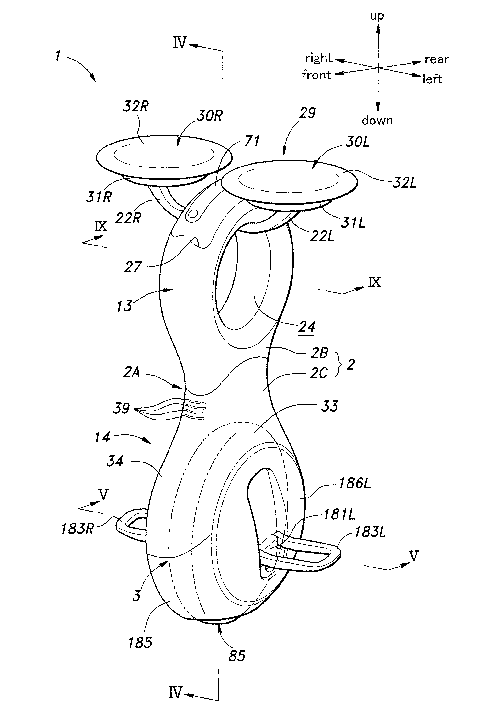
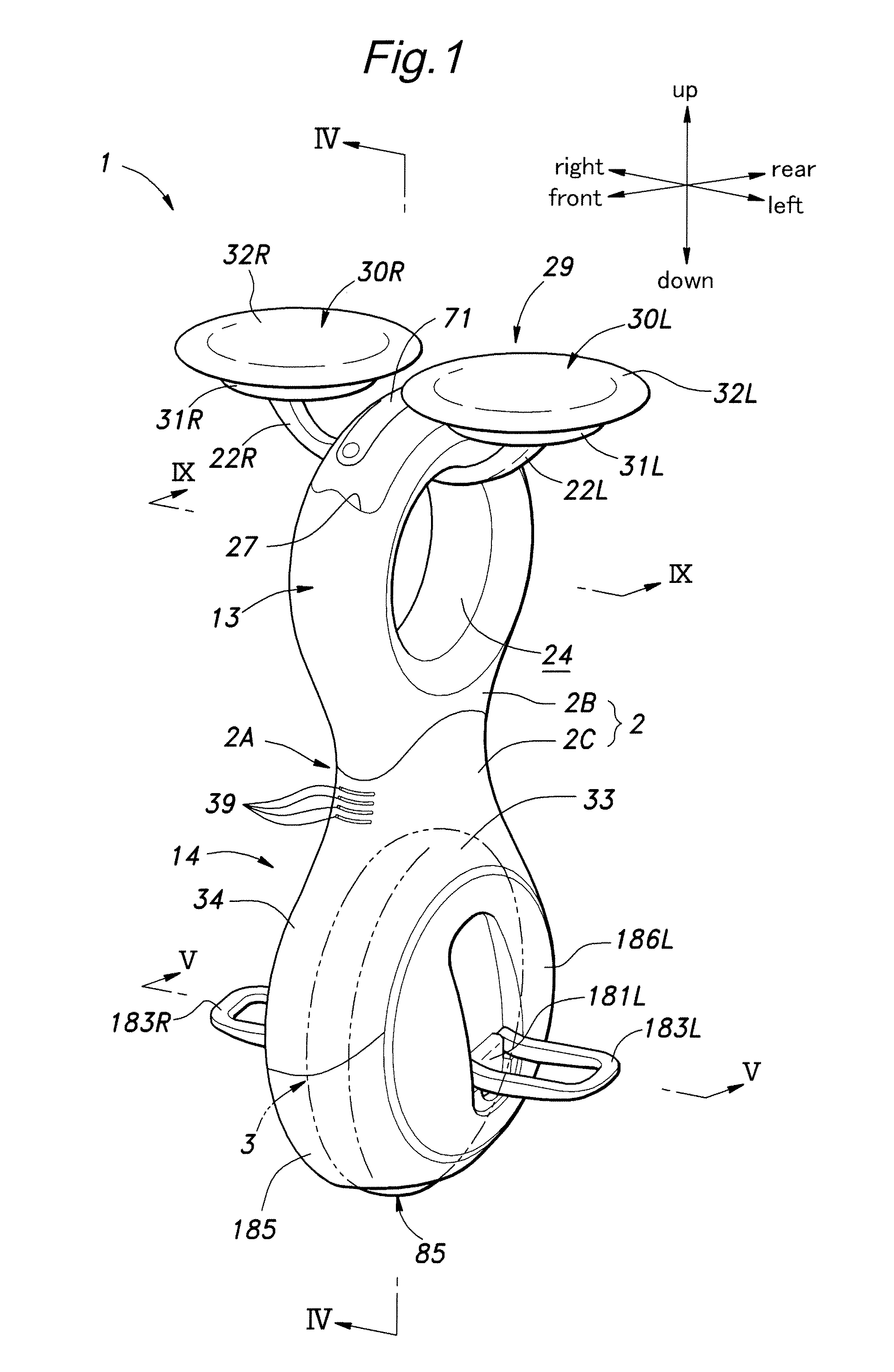
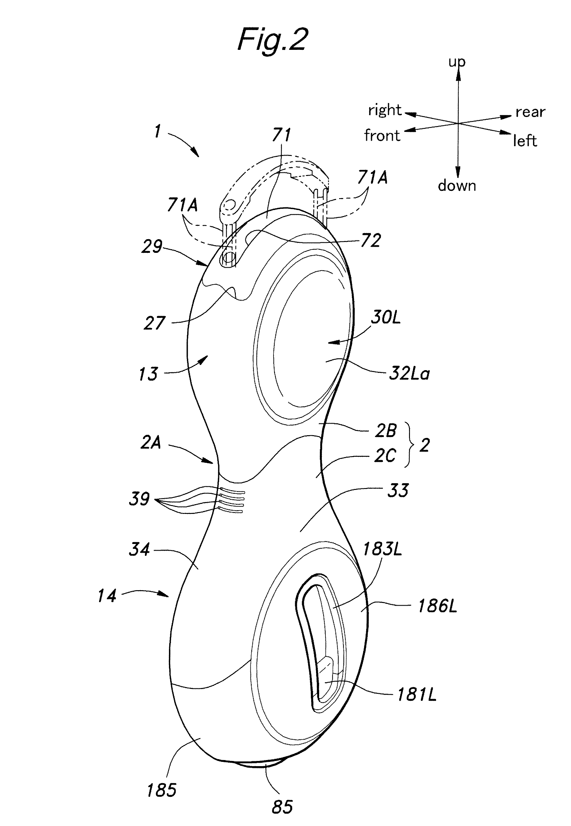
[0037]The vehicle according to the present invention is in large part symmetric with respect to a central longitudinal plane, and various components are used in pairs, one on the right hand side and the other on the left hand side. Such components are denoted with numerals with a suffix L or R, L indicating the component being on the left hand side and R indicating the component being on the right hand side. Therefore, only one of each of such pairs may be described in the following by denoting the component with a numeral without a suffix, instead of repeating the same description with respect to the other of the pair. These numerals are also used without the suffix in the following description to denote such components collectively.

[0038]Referring to FIGS. 1 to 6, the inverted pendulum type vehicle 1 given as a first embodiment of the present invention comprises a frame 2 elongated in a vertical direction, a drive unit 3 incorporated in a lower part of the frame 2, a seat assembly...


PUM

PropertyMeasurementUnit
speed ratioaaaaaaaaaa
speedaaaaaaaaaa
circumferenceaaaaaaaaaa

Abstract

A frictional drive device comprises a pair of drive disks (48) each rotatably supported by a frame (2, 42) around a central axial line (A) in a mutually opposing relationship, and a pair of actuators (64) supported by the frame for individually rotatively actuating the drive disks and coaxially disposed with respect to the corresponding drive disks, a plurality of drive rollers (56) arranged along an outer periphery of each drive disk and each having a rotational center line so as to be rotatable along a plane which is neither parallel nor perpendicular to the central axial line, and an annular main wheel (85) disposed approximately coaxially with respect to the central axial line and engaged by the drive rollers of the drive disks, the main wheel comprising an annular member (86) and a plurality of driven rollers (92) supported along the annular member so as to be rotatable around a tangential line of the annular member. A speed reduction unit (72, 100) may be interposed between each actuator and the corresponding drive disk all in a coaxial relationship.

Description

TECHNICAL FIELD[0001]The present invention relates to a frictional drive device and an inverted pendulum type vehicle using the same, and in particular to a frictional drive device suitable for use as a propulsion device for a vehicle and an inverted pendulum type vehicle using the same.BACKGROUND OF THE INVENTION[0002]Known is an inverted pendulum type vehicle or an omni-directional vehicle comprising a pair of drive assemblies individually actuated by electric motors and a main wheel held between the drive assemblies and frictionally driven by the drive assemblies. See WO2008132779A1 (US20100096905A1) (patent document 1) for instance. Each drive assembly comprises a drive disk coaxially opposing the drive disk of the other drive assembly and a plurality of drive rollers obliquely arranged along the circumference of the drive disk at a regular interval so as to be individually rotatable. The main wheel comprises a ring-shaped annular member rotatably supported by a frame around a c...

Claims


Application Information

Patent Timeline
Patent Type & Authority Applications(United States)
IPC IPC(8): B62K11/00F16H13/04F16H37/02B62K1/00
CPCB60B19/003Y10T74/19B60B2200/47B60B2310/204B60B2310/228B60B2310/232B60B2310/305B60B2360/10B60B2360/147B60B2360/32B60B2360/348B60B2360/50B60B2380/12B60B2380/14B62K1/00B62K3/007B60B19/125B60L1/003B60L3/0061B60L2200/14B60L2220/42B60L2240/425B60L2240/461B60L2260/34B62K11/007B60L50/51B60L58/12B60L50/66Y02T10/64Y02T10/70
Inventor GOMI, HIROSHIKOBASHI, SHINICHIROTAKENAKA, TORUAKIMOTO, KAZUSHIUEBAYASHI, YUICHIHAMAYA, KAZUSHIYADA, WATARUWAITA, HIRONORI
Owner HONDA MOTOR CO LTD
Why Eureka
Try Eureka