A Prediction Method in Video Compression

A prediction method and video compression technology, applied in the fields of digital video signal modification, image communication, electrical components, etc., can solve the problems of bus bandwidth and power consumption shock, inability to reduce theoretical limit entropy, and increase in chip area cost, etc. performance, good prediction direction correction effect, and the effect of improving accuracy

Active Publication Date: 2020-08-11
苏州龙盈软件开发有限公司
View PDF5 Cites 0 Cited by
  • Summary
  • Abstract
  • Description
  • Claims
  • Application Information

AI Technical Summary

Problems solved by technology

For video processing chips, the multiple increase in resolution will not only cause a substantial increase in chip area cost, but also have a great impact on bus bandwidth and power consumption
[0003] Complex textures in images are divided into artificial textures and natural textures. The existing technology cannot guarantee to find the most suitable reference pixels for the prediction of artificial textures, and cannot reduce the theoretical limit entropy, so that the most superior prediction method cannot be selected.

Method used


Image

  • A Prediction Method in Video Compression
  • A Prediction Method in Video Compression
  • A Prediction Method in Video Compression

Examples


Embodiment 1

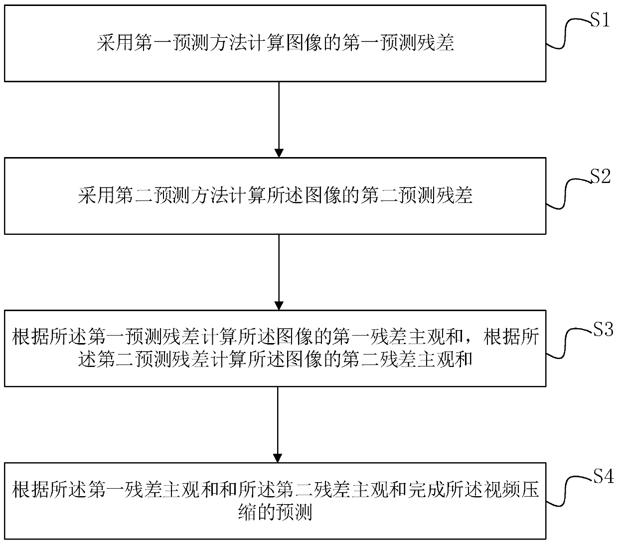
[0056] See figure 1 , figure 1 It is a schematic flow chart of a prediction method in video compression

[0057] A method for predicting video compression, comprising the following steps:

[0058] S1. Using the first prediction method to calculate the first prediction residual of the image

[0059] S2. Using a second prediction method to calculate a second prediction residual of the image;

[0060] S3. Calculate the first residual subjective sum of the image according to the first prediction residual, and calculate the second residual subjective sum of the image according to the second prediction residual;

[0061] S4. Complete the video compression prediction according to the first residual subjective sum and the second residual subjective sum.

[0062] In the embodiment of the present invention, two prediction residual results of the image are respectively calculated by two prediction methods, and two different residual subjective sums are respectively calculated according...

Embodiment 2

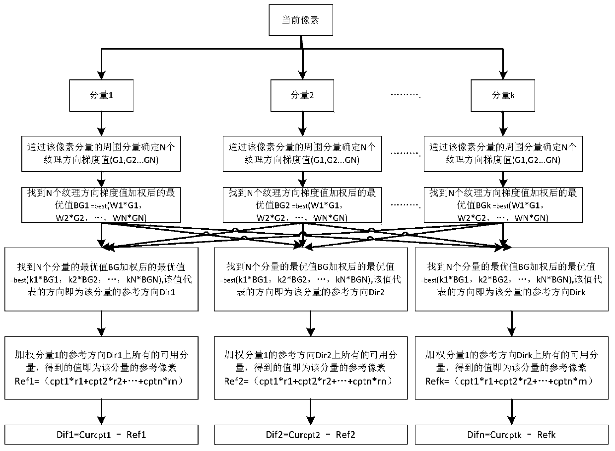
[0064] See figure 2 , figure 2 It is an algorithm principle diagram of a first prediction method of a video compression prediction method provided by an embodiment of the present invention. In this embodiment, on the basis of the foregoing embodiments, the video compression prediction method will be described in detail.

[0065] S1. adopting the first prediction method to calculate the first prediction residual error of the image, comprising the following steps:

[0066] S11. Obtain multiple pixel components k of the current pixel, where k≥1;

[0067] S12. Obtain the texture direction gradient values ​​of the plurality of pixel components, and for each pixel component of the current pixel, determine the N number of each pixel component by determining the surrounding pixel components of each pixel component The gradient value of the texture direction, the gradient value is represented by G1-GN, and the gradient value of the texture direction of the plurality of pixel compo...

Embodiment 3

[0133] In this embodiment, on the basis of the above embodiments, the current pixel is divided into three pixel components of Y, U, and V to describe the first prediction method in detail, and the specific implementation manner is as follows.

[0134] Divide the current pixel into three pixel components, namely pixel component Y, pixel component U, and pixel component V.

[0135] The gradient values ​​G1, G2, and G3 of the three texture directions are determined by surrounding pixel components of the three pixel components of the current pixel.

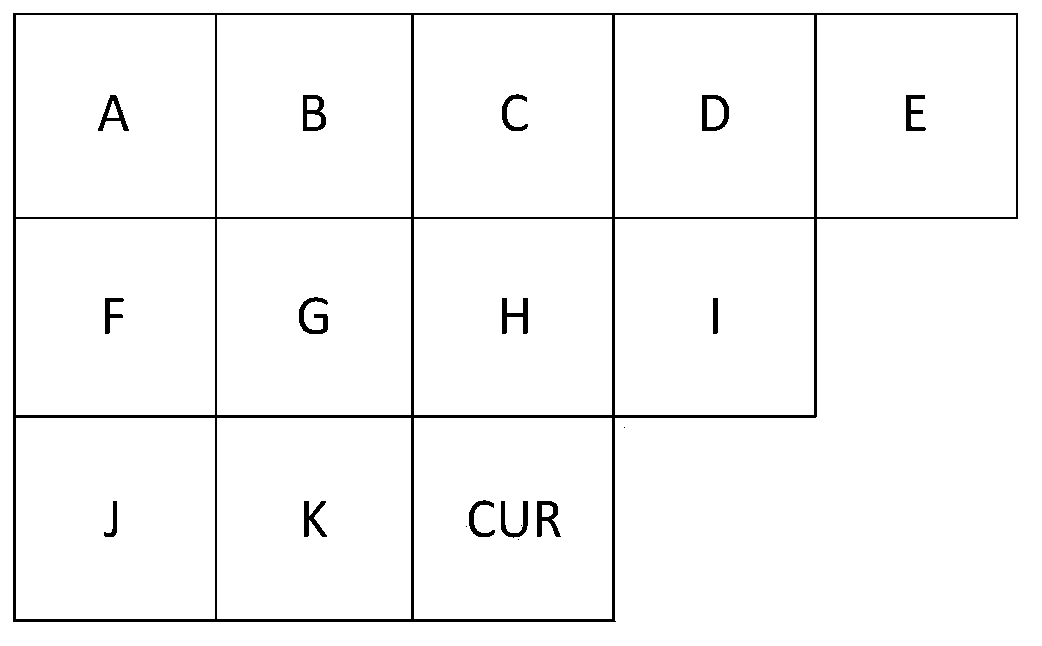
[0136] See Image 6 , Image 6 A schematic diagram of a gradient value calculation of a video compression prediction method provided by an embodiment of the present invention; in a specific embodiment, for the three pixel components of Y, U, and V, ABS (K-H) is a gradient value of 45 degrees, ABS (K-G) is a 90-degree gradient value, ABS (K-F) is a 135-degree gradient value, and ABS (K-J) is a 180-degree gradient value.

[0137] See...


PUM


Abstract

The invention relates to a prediction method in video compression. The method comprises the steps of S1, calculating first prediction residuals of an image by adopting a first prediction method; S2, calculating second prediction residuals of the image by adopting a second prediction method; S3, calculating the first subjective difference of the image according to the first prediction residuals, and calculating the second subjective difference of the image according to the second prediction residuals; and S4, completing the prediction of the video compression according the first subjective difference and the second subjective difference. A pixel-level adaptive direction prediction method referred to multiple pixel components reduces the possibility of misjudgment of single pixel component prediction; and an adaptive texture gradual change prediction method in bandwidth compression adaptively obtains the minimum prediction residual according to texture characteristics of the current macro block at the texture boundary of the image to be compressed so as to increase the bandwidth compression rate. The image is respectively predicted according to the two prediction methods, and the best prediction method is selected to serve as a prediction method in the video compression.

Description

technical field [0001] The invention belongs to the field of video compression, and in particular relates to a prediction method in video compression. Background technique [0002] With the gradual increase of people's demand for video quality, video image resolution, as one of the important characteristics of video quality, has transitioned from 720p and 1080p to the current mainstream 4K video resolution in the market, and the corresponding video compression standard has also changed from H. 264 to H.265. For video processing chips, the multiple increase in resolution will not only cause a substantial increase in chip area cost, but also have a great impact on bus bandwidth and power consumption. [0003] Complex textures in images are divided into artificial textures and natural textures. For the prediction of artificial textures, the existing technology cannot guarantee to find the most suitable reference pixels and cannot reduce the theoretical limit entropy, so it is ...

Claims


Application Information

Patent Timeline
Patent Type & Authority Patents(China)
IPC IPC(8): H04N19/103H04N19/50H04N19/176H04N19/182H04N19/132
CPCH04N19/103H04N19/132H04N19/176H04N19/182H04N19/50
Inventor 冉文方李雯
Owner 苏州龙盈软件开发有限公司
Why Eureka
Try Eureka