Buoy having tube part and method for manufacturing same

A technology of buoys and tubes, applied in the field of buoys and their manufacture, can solve the problems of low productivity, fragmentation, and negligible effect of marine pollution prevention, and achieve the effect of easy reuse

Active Publication Date: 2019-04-02
CLIFE +1
View PDF21 Cites 0 Cited by
  • Summary
  • Abstract
  • Description
  • Claims
  • Application Information

AI Technical Summary

Problems solved by technology

However, even when polypropylene is used, fragments may be generated when receiving a strong impact, so there is a problem that the effect of preventing marine pollution is minimal and productivity is low

Method used


Image

  • Buoy having tube part and method for manufacturing same
  • Buoy having tube part and method for manufacturing same
  • Buoy having tube part and method for manufacturing same

Examples


Embodiment Construction

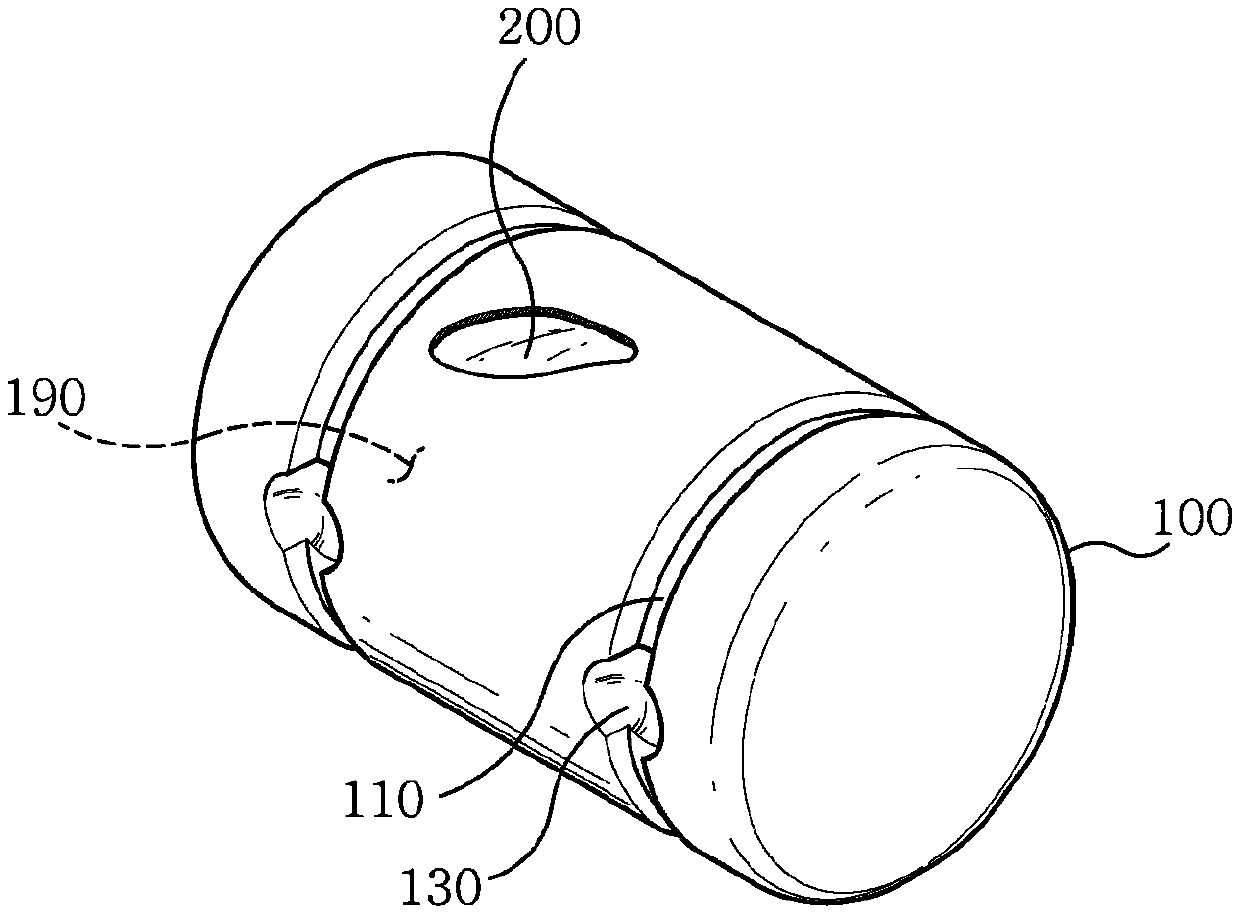
[0028] figure 1 It is a perspective view illustrating a buoy to which the present invention is applied. exist figure 1 In FIG. 2 , a state in which a part of the jacket portion 100 is cut away is shown in order to show the pipe portion 200 .

[0029] figure 1 The buoy shown in FIG. 2 can include an envelope part 100 and a tube part 200 .

[0030] The cuff part 100 can consist of a cylindrical shape with a central bore 109 sealed from the outside. As an example, the cuff portion 100 can be manufactured in a cylindrical shape, a spherical shape, or the like.

[0031] The cuff portion 100 with the sealed bore 109 can itself be buoyant. However, when manufacturing the buoy using only the envelope portion 100 , it is necessary to increase the thickness of the envelope portion 100 in order to avoid changes in the shape of the envelope portion 100 . In addition, because the envelope part 100 forms the shape of a buoy and is directly exposed to the external environment, it is su...


PUM


Abstract

A buoy, according to the present invention, comprises: a cylinder-shaped cover part having a hollow which is sealed off from the outside; and a tube part, formed from a flexible material, provided inthe hollow and expanding by means of gas injection, wherein the expanded tube part can come in physical contact with the inner side of the cover part and transform in accordance with the inner side ofthe cover part.

Description

technical field [0001] The invention relates to a buoy capable of floating on water and a manufacturing method thereof. Background technique [0002] In the sea area of ​​the coastal area, many marine life farms are operated in which fish, shellfish, and seaweed are cultured in the inside of the fishing net or on the breeding board by hanging the fishing net or the breeding board on the floating body. [0003] Floating bodies are an essential component when installing fishing nets or culture plates, but they are also criticized as the main cause of marine pollution. [0004] In order to solve the problem of ocean pollution, polypropylene material can be used to replace the existing floating body made of foamed polystyrene. However, even when polypropylene is used, fragments may be generated when receiving a strong impact, so there is a problem that the effect of preventing marine pollution is minimal and productivity is low. Contents of the invention [0005] technical i...

Claims


Application Information

Patent Timeline
Patent Type & Authority Applications(China)
IPC IPC(8): A01K61/60A01G33/00B63B22/00
CPCA01K61/00A01K75/04B63B22/00Y02A40/81
Inventor 金永根
Owner CLIFE
Why Eureka
Try Eureka