
Physical examination bed for obstetrics and gynecology department

A medical examination bed, obstetrics and gynecology technology, applied in the field of medical devices, can solve problems such as adverse effects on the fetus, fatigue, inconvenient adjustment of the height of the pad, and achieve the effect of easy inspection

Inactive Publication Date: 2019-04-05
亓琳
View PDF10 Cites 18 Cited by
  • Summary
  • Abstract
  • Description
  • Claims
  • Application Information

AI Technical Summary

Problems solved by technology

In the current routine examination, the general hospital bed is used, but when the pregnant woman is checking the body, she needs to lie on the examination bed to support her legs, so as to facilitate the doctor's examination, but the conventional examination bed does not have this function, and it takes a long time Keeping the posture of raising the legs for a long time will cause fatigue, especially for pregnant women. Usually, they can only be raised by placing pillows on the examination bed, but the height of the cushion is inconvenient to adjust, which makes it easy for pregnant women to check the abdomen. It will cause adverse effects on the fetus, and it is inconvenient for doctors to use medical equipment during operation; and the existing examination bed is not equipped with structures such as shielding curtains, and there may be other people during the examination, which will make pregnant women feel uncomfortable

Method used


Image

  • Physical examination bed for obstetrics and gynecology department
  • Physical examination bed for obstetrics and gynecology department
  • Physical examination bed for obstetrics and gynecology department

Examples


Embodiment 1

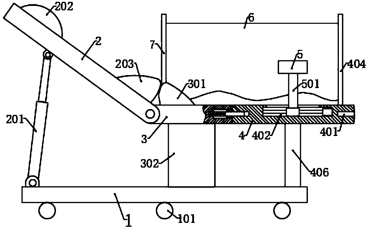
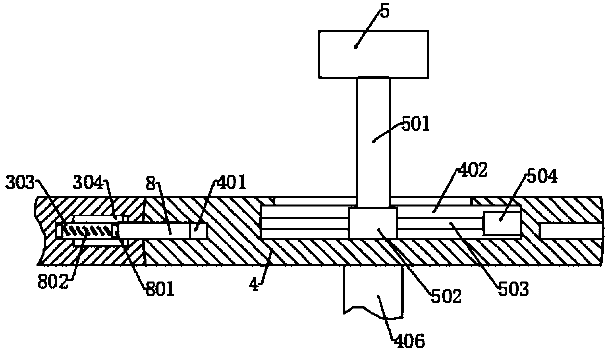
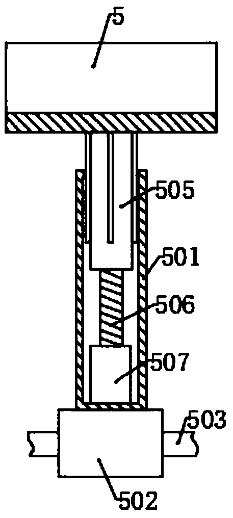
[0024] Please refer to the accompanying drawings, the present invention provides a technical solution: a bed for obstetrics and gynecology, including a bottom frame 1, a seat board 3, a back board 2 and a turning board 4, and the two sides of the back board 2 are connected to the bottom by a support board 302 The frame 1 is fixedly connected, the left end of the back plate 2 is rotationally connected with the seat plate 3, and two hydraulic telescopic rods 201 are rotationally connected on the left side of the bottom surface, the bottom ends of the hydraulic telescopic rods 201 are rotationally connected with the bottom frame 1, and the flip plate 4 is arranged on The right side of the seat plate 3, and the front and rear sides of the turnover plate 4 are respectively rotated and connected with a support rod 406. A moving slot 402, a screw mandrel 503 is rotatably connected in the moving slot 402, and one end of the screw mandrel 503 is connected with a moving motor 504, the sc...

Embodiment 2

[0028] On the basis of Embodiment 1, the left and right sides of the turning board 4 are set as arc surfaces, and the middle of the arc surfaces is provided with a second slot 401, and the right side of the seat plate 3 is correspondingly set as arc surfaces. And the center of arc surface is provided with the first draw-in groove 303, and the upper and lower side of the first draw-in groove 303 is symmetrically provided with limit groove 304, is slidably connected with clamping plate 8 in the first engaging groove 303, and the right end of clamping plate 8 stretches into turning over In one of the second slots 401 of the board 4, an electromagnet 801 is fixed in the middle of the left end, and first springs 802 are arranged on both sides, and are connected to the left side wall of the first slot 303 through the first springs 802, and the first A permanent magnet is arranged on the left side wall of the slot 303 .

[0029]When the turnover plate 4 needs to rotate, the electroma...

Embodiment 3

[0031] On the basis of the second embodiment, the top side of the turnover plate 4 is also provided with a storage groove 403, and the notch of the storage groove 403 has a cover plate 404 for damping rotation, and a pull cord is fixed on the cover plate 404. There is a shielding curtain 6, and there are three hanging rings on the other end of the pull cord and on both sides of the middle, and there is a hanging rod on the side of the turnover plate 4 far away from the storage groove 403 for damping rotation, and the two sides of the seat board 3 are respectively fixed with fixed cylinders 704, the bottom of the fixed cylinder 704 is connected with the first air pump 705, the fixed cylinder 704 is provided with a movable plate 702, the movable plate 702 is provided with a sealing ring, and is connected with the inner side wall of the fixed cylinder 704 through the sealing ring, the movable plate 702 Top surface is fixed with elevating rod 7, and the top of elevating rod 7 stret...


PUM


Abstract

The invention discloses a physical examination bed for obstetrics and gynecology department. The physical examination bed comprises a bottom frame, a seat plate, a back plate and a turning plate. Through a turning motor, the turning plate rotates for 180 degrees; one side provided with the placing plate faces the upward direction; a lead screw is driven to rotate through a moving motor, so that the placing plate is driven to move through structures of moving blocks, moving tubes and the like; then, through an ascending and descending motor, a threaded rod rotates; a threaded tube can only vertically move through the effects of slide strips and slide grooves. Therefore when the threaded rod rotates, the threaded tube drives the placing plate to move, so that the position of the placing plate can be regulated, so that the position of the placing plate is convenient for examination; when the leg support is not needed, one side, provided with the placing plate, of the turning plate faces the downward direction; the other side surface faces the upward direction; the bed is used as an ordinary examination bed or a sickbed; the leg placing inconvenience of a pregnant woman due to the blockage by the placing plate can be avoided; the angle of the back plate is regulated through a hydraulic telescopic rod, so that the lying feeling of the pregnant woman is more comfortable.

Description

technical field [0001] The invention relates to the technical field of medical devices, in particular to an obstetrics and gynecology examination bed. Background technique [0002] Obstetrics and Gynecology is one of the four main disciplines of clinical medicine. It mainly studies the etiology, pathology, diagnosis and prevention of female reproductive organ diseases, the physiological and pathological changes of pregnancy and childbirth, the prevention, diagnosis and treatment of high-risk pregnancy and dystocia, female reproductive endocrinology, Family planning and women's health care. The in-depth study of basic medical theories such as modern molecular biology, oncology, genetics, reproductive endocrinology and immunology and the advancement of clinical medical diagnosis and treatment detection technology have broadened and deepened the development of obstetrics and gynecology, and ensured women's physical and reproductive health. It plays an important role in the pre...

Claims


Application Information

Patent Timeline
IPC IPC(8): A61G13/08A61G13/10A61G13/12
CPCA61G13/0018A61G13/08A61G13/10A61G13/121A61G13/1225A61G13/1245A61G13/1265A61G2200/12
Inventor 亓琳
Owner 亓琳
Learn More