

Bearing disassembly device with regulating function
A bearing disassembly device and functional technology, which is applied in the manufacture of tools, transportation and packaging, metal processing, etc., can solve the problems of violent damage to bearings, waste of disassembly time, etc., and achieve the effect of facilitating disassembly work and improving the stability of up and down movement
- Summary
- Abstract
- Description
- Claims
- Application Information
AI Technical Summary
Problems solved by technology
Method used
Image

Examples
Embodiment Construction
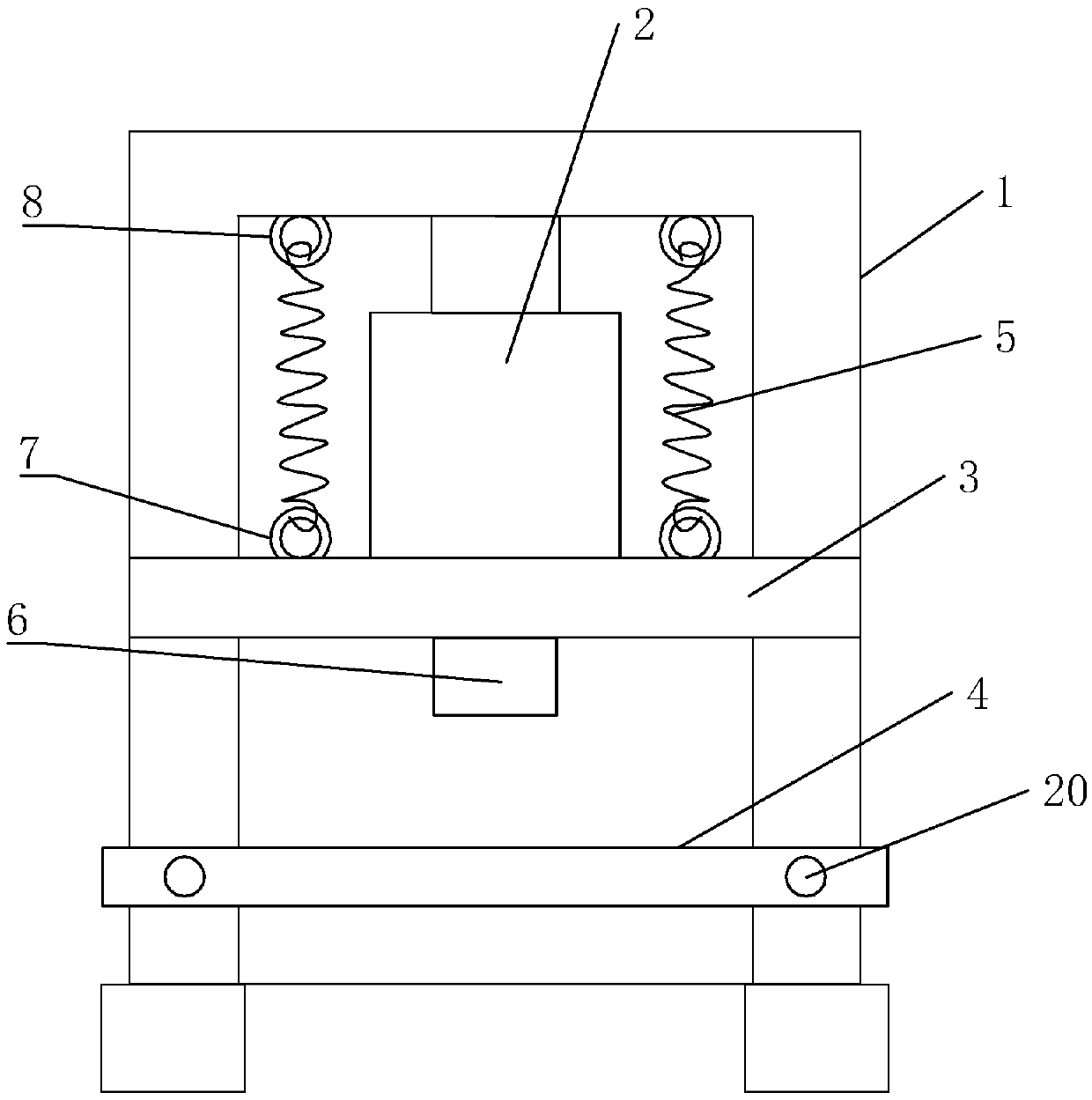
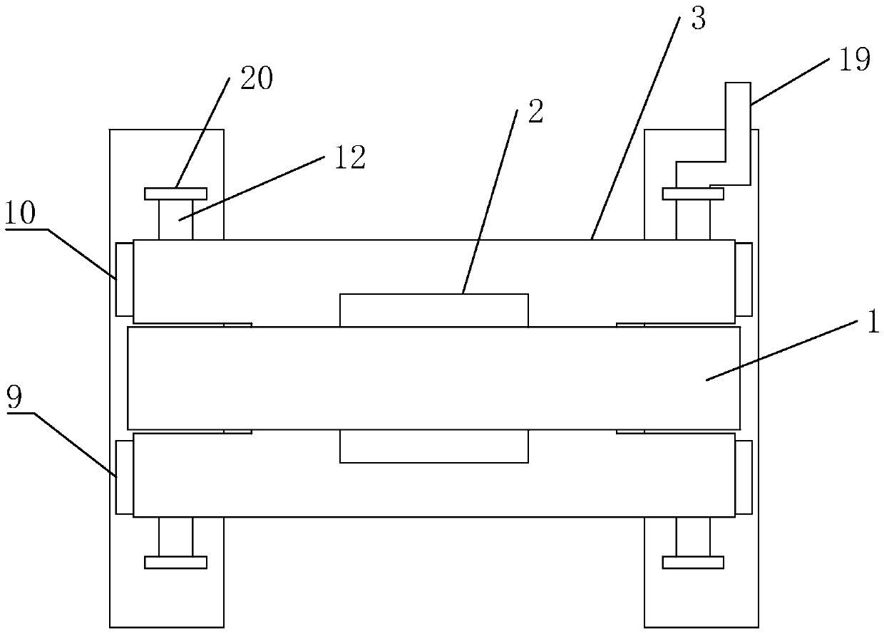
[0021] refer to Figures 1 to 5 As shown, a bearing removal device with adjustment function in this embodiment includes a frame body 1, a push rod 2, a sliding plate 3, a fixing plate 4 and a tension spring 5, the frame body 1 is arranged in a frame shape, and the The push rod 2 is arranged on the top of the frame body 1, the sliding plate 3 is slidably installed between the two vertical support rods of the frame body 1, the bottom of the push rod 2 is connected with the sliding plate 3, and the sliding plate is driven by the push rod 2 Plate 3 moves on frame body 1, and described extension spring 5 is provided with two, and two extension springs 5 are symmetrically arranged on sliding plate 3, and extension spring 5 is connected with the top of frame body 1 respectively, and described fixed plate 4 is arranged at the bottom of the frame body 1, and the sliding plate 3 is set in cooperation with the fixed plate 4,
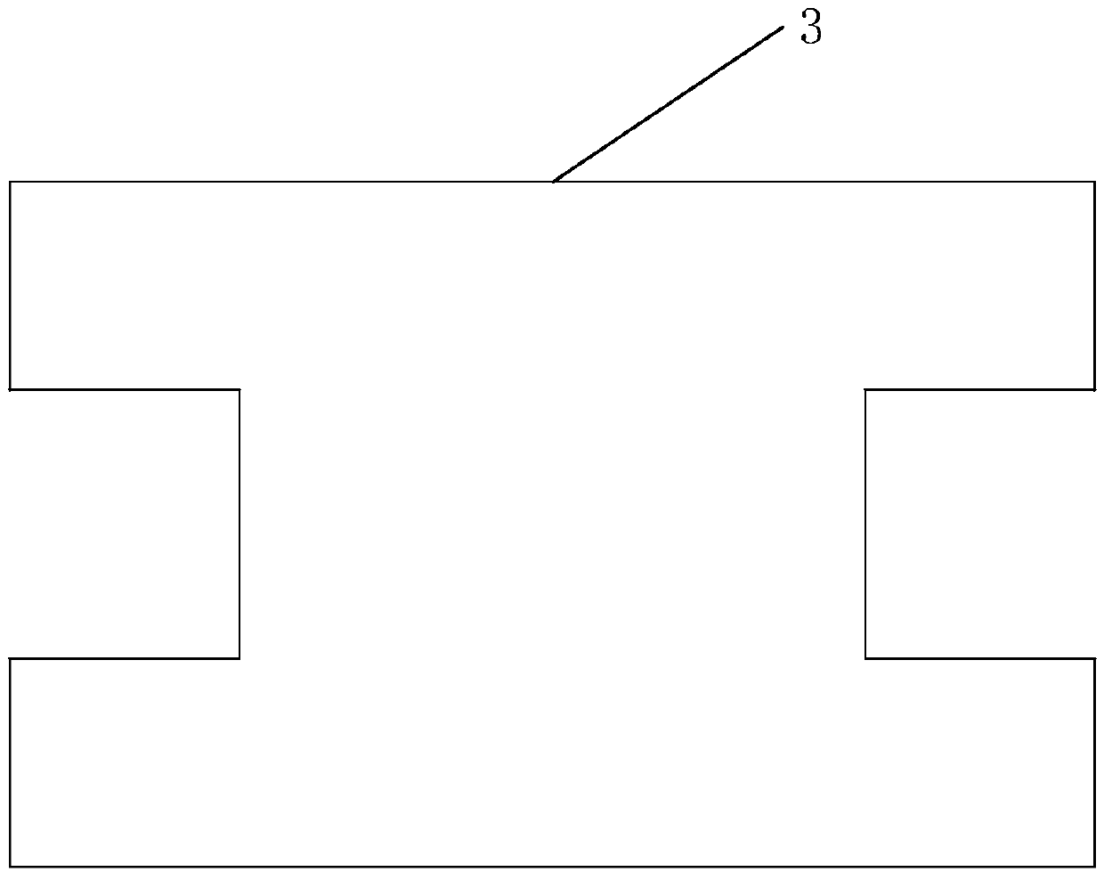
[0022] Such as Figure 4-5 As shown, the fixed plate 4 in...
PUM
 Abstract
Description
Claims
Application Information