Ultra-high-pressure pressure relief pump

A pressure relief pump and ultra-high pressure technology, which is applied in the field of pressure relief pumps, can solve the problems of harsh pressure relief components and large oil pressure variation range, and achieve the effects of fast pressure relief, slow pressure relief, and quick response

Active Publication Date: 2019-04-05
胡海明
View PDF4 Cites 1 Cited by
  • Summary
  • Abstract
  • Description
  • Claims
  • Application Information

AI Technical Summary

Problems solved by technology

[0003] However, since the oil pressure of the compressor varies in a very large range during the pressure relief process, and the pressure value changes with time during the pressure relief process according to the diamond synthesis process, it is necessary to achieve a full pressure relief speed at high pressure (100MPa-40MPa). As time goes by, the pressure decreases, and the pressure relief speed needs to be faster at low pressure (40MPa-6MPa), which puts forward very strict requirements on the pressure relief components and control

Method used


Image

  • Ultra-high-pressure pressure relief pump
  • Ultra-high-pressure pressure relief pump
  • Ultra-high-pressure pressure relief pump

Examples


Embodiment Construction

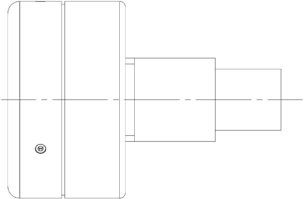
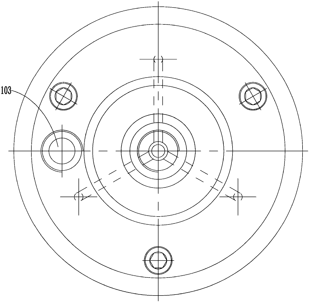
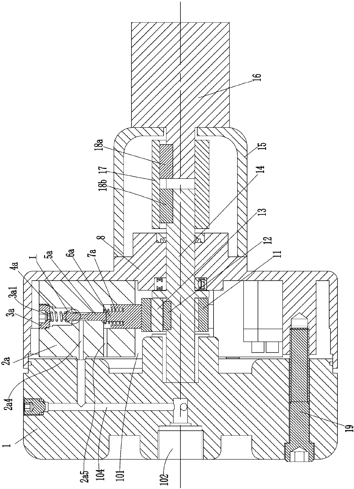
[0028] see Figure 1-8 As shown, an ultra-high pressure relief pump includes a pump body 1, and a pump casing 8 installed on the right end surface of the pump body 1 through bolts 19, and an oil discharge is formed between the pump casing 8 and the right end surface of the pump body 1. Chamber 101; the right end surface of the pump body 1 is rotatably connected with a rotating shaft 14 protruding from the pump casing 8, and three pressure relief chambers are evenly installed on the right end surface of the pump body 1 in the oil drain chamber 101 with the rotating shaft 14 as the center. Module 3, the first shaft sleeve 13 is installed eccentrically on the rotating shaft 14 through the first pin key 12 in the oil drain chamber 101, and the second shaft sleeve 13 with a regular hexagonal cross section is rotatably connected to the first shaft sleeve 13. Shaft sleeve 11.

[0029] The pressure relief module 3 includes a pressure relief cylinder 2a, a pressure relief valve core 5...


PUM


Abstract

The invention discloses an ultra-high-pressure pressure relief pump. The ultra-high-pressure pressure relief pump comprises a pump body and a pump shell mounted on the right end surface of the pump body, an oil discharge cavity is formed between the pump shell and the right end surface of the pump body, a rotating shaft extending out of the pump shell is rotatably connected with the right end surface of the pump body, a plurality of pressure relief modules are evenly installed at the position, located in the oil discharge cavity, on the right end surface of the pump body with the rotating shaft as the center at intervals, and a first shaft sleeve and a second shaft sleeve rotatably connected with the first shaft sleeve and with the orthohexagonal cross section are eccentrically and fixedlymounted on the position, located on rotating shaft, in the oil discharge cavity; and each pressure relief module comprises a pressure relief cylinder body, a pressure relief valve core, a pressure relief spring, a pressure relief screw plug, an ejecting block, and a compaction spring, an A oil opening is formed in the left end surface of the pump body, a third communicating hole is formed in thepump body, and a B oil opening communicated with the oil discharge cavity is formed in the pump body. The ultra-high-pressure pressure relief pump is not only compact in volume and low in cost, but also can achieve slowly relieve the pressure at the high pressure, and slowly increase the pressure relief speed over time.

Description

technical field [0001] The invention relates to the technical field of pressure relief pumps, in particular to an ultrahigh pressure relief pump. Background technique [0002] The synthesis equipment of synthetic diamond in my country is a six-sided top press, which uses an ultra-high pressure hydraulic system with an oil pressure of up to 100MPa. The ultra-high pressure oil pump it is equipped with can directly output oil pressure up to 100MPa to the working cylinder of the six-sided top press, and it needs to be released from the ultra-high pressure pipeline to reduce the pressure after the pressing work of the press is completed. At present, the ultra-high pressure pressure relief system of the six-sided top press basically uses the electromagnetic reversing valve to control the on-off of the single-stage pressure relief valve to achieve pressure relief. The small liquid flow damping hole is used to control the return flow rate of the drained oil to reduce the impact of ...

Claims


Application Information

Patent Timeline
IPC IPC(8): F04B53/10B01J3/06
CPCB01J3/065F04B53/10
Inventor 不公告发明人
Owner 胡海明
Why Eureka
Try Eureka