Optical lens ultrasonic cleaning jig based on elastic deformation and sliding extrusion

A technology of optical lens and elastic deformation, applied in cleaning methods and utensils, cleaning methods using liquids, chemical instruments and methods, etc., can solve problems such as damage, inaccessibility of lenses, impact, etc., and achieve the effect of preventing accidental shedding

Active Publication Date: 2019-04-09
浙江思密达智能装备有限公司
View PDF7 Cites 6 Cited by
  • Summary
  • Abstract
  • Description
  • Claims
  • Application Information

AI Technical Summary

Problems solved by technology

[0006] In view of the deficiencies in the prior art, the purpose of the present invention is to provide an ultrasonic cleaning fixture for optical lenses based on elastic deformation and sliding extrusion, to solve the problem that the receiving device is generally a multi-grid straight cylinder structure. There is not much gap with the straight barrel structure, so the lens cannot be inserted together with your fingers. When placing the lens, you need to let go of your fingers, which will cause the lens to slide directly to the bottom. Under the acceleration of gravity, it will bump the lens. In order to make the lens can be taken out, the lens and the straight barrel structure There is a gap. When moving, the lens will continue to collide with the placement device. At the same time, if it is accidentally tilted, the lens will slide out directly and cause damage.

Method used


Image

  • Optical lens ultrasonic cleaning jig based on elastic deformation and sliding extrusion
  • Optical lens ultrasonic cleaning jig based on elastic deformation and sliding extrusion
  • Optical lens ultrasonic cleaning jig based on elastic deformation and sliding extrusion

Examples


Embodiment Construction

[0030] In order to make the technical means, creative features, goals and effects achieved by the present invention easy to understand, the present invention will be further described below in conjunction with specific embodiments.

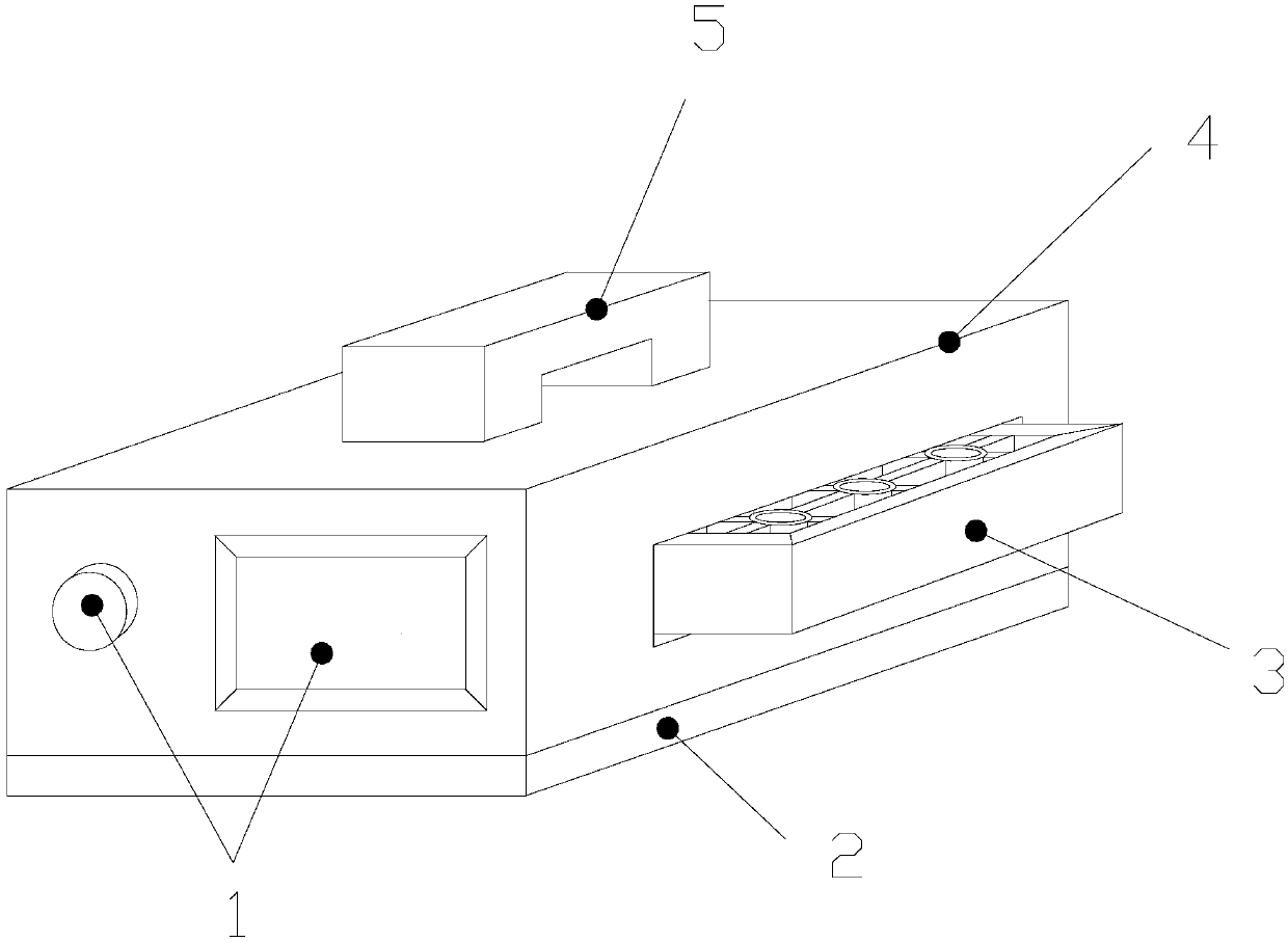
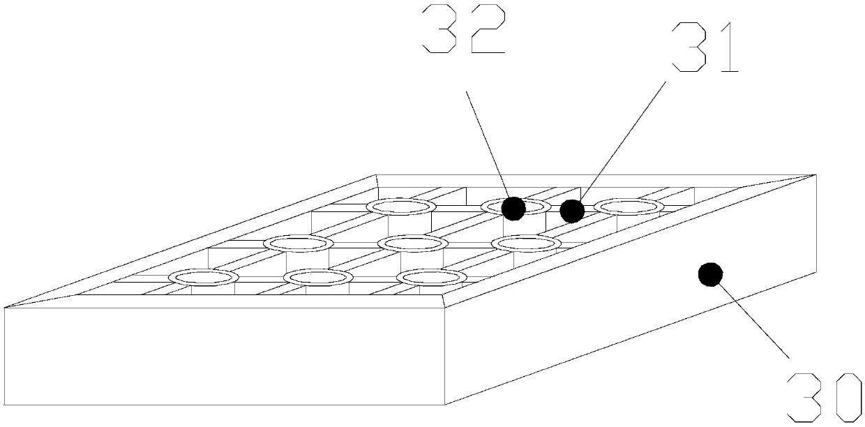
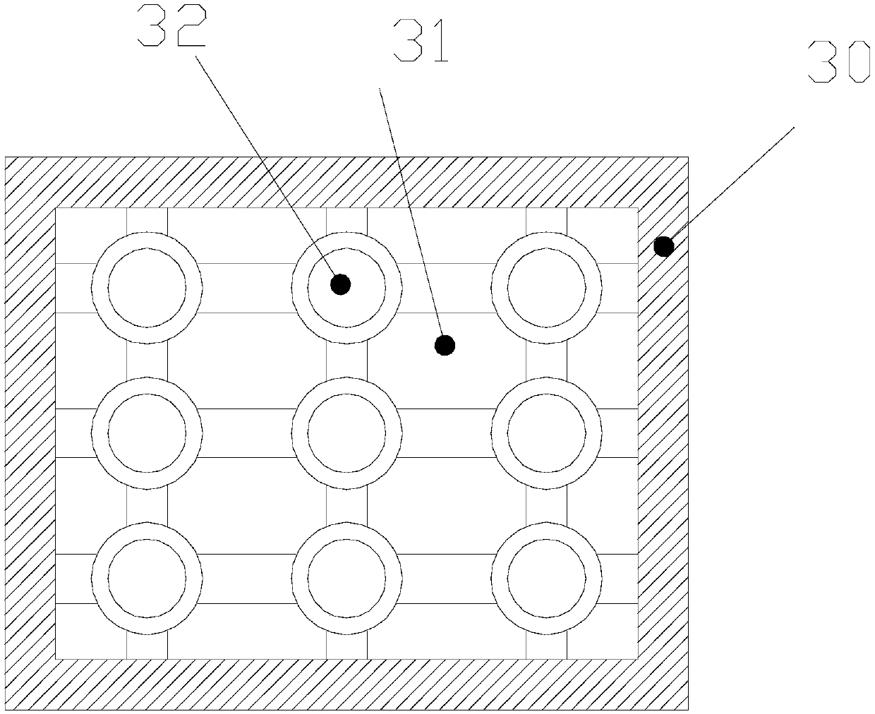
[0031] see Figure 1-Figure 4 , the present invention provides a technical scheme of an ultrasonic cleaning fixture for optical lenses based on elastic deformation and sliding extrusion: its structure includes a control switch 1, a base 2, a lens storage box 3, an ultrasonic cleaner 4, and a handle 5. The control The rear end of the switch 1 and the front end of the ultrasonic cleaner 4 are an integrated structure, the bottom of the ultrasonic cleaner 4 is fixedly connected to the top of the base 2 by screws, the inside of the control switch 1 is electrically connected to the inside of the ultrasonic cleaner 4, and the ultrasonic cleaner 4 is electrically connected. The middle end of the cleaner 4 is connected to the left end of the lens storage b...


PUM


Abstract

The invention discloses an optical lens ultrasonic cleaning jig based on elastic deformation and sliding extrusion. The optical lens ultrasonic cleaning jig structurally comprises control switches, abase, a lens placement box, an ultrasonic cleaner and a handle. An elastic plate is made of a plastic material and forms a certain oblique angle with a groove base frame. When a lens slides down, inwards concave folding of return springs can be offset, instant impact between the lens and an elastic film during contact is reduced, the lens slides on the elastic film, a sliding unloading wheel and alinkage block offset a spring rod jointly to slide down by extruding the elastic film through the lens, a small rolling wheel is connected to the bottom of the elastic film, thus, the lower end of the elastic film can be expanded outwards in cooperation with extrusion of the lens, the lens is further prevented from directly falling to the bottom due to the acceleration of gravity, after the lensis stopped, the linkage block slides down by a certain distance, meanwhile, a movable chain and an auxiliary pulley rotate anticlockwise together, a pulling rope between the auxiliary pulley and the elastic plate is loosened, the elastic plate is extruded by the return springs to extend outwards, the top of the lens can be clamped, the lens is prevented from accidentally falling down, and the lenstends to be stable through elastic deformation of the elastic film and does not swing left and right at the same time.

Description

technical field [0001] The invention relates to an ultrasonic cleaning jig for optical lenses based on elastic deformation and sliding extrusion, and belongs to the field of ultrasonic cleaning jigs. Background technique [0002] As a high-precision microscopic equipment, optical lenses cannot be directly scrubbed with water during cleaning. Ultrasonic cleaning fixtures are required to clean optical lenses. Clean the inside of the jig. [0003] However, the existing ultrasonic cleaning fixtures have the following disadvantages: [0004] 1. The receiving device is generally a multi-grid straight cylinder structure. When placing the optical lens, because the gap between the lens and the straight cylinder structure is not large, the lens cannot be entered together with the fingers. When placing the lens, the finger must be released, and the lens will directly slide down to the bottom , under the acceleration of gravity, it will collide with the lens. [0005] 2. In order to ...

Claims


Application Information

Patent Timeline
Patent Type & Authority Applications(China)
IPC IPC(8): B08B7/02B08B3/12B08B13/00
CPCB08B3/12B08B7/028B08B13/00
Inventor 黄海燕
Owner 浙江思密达智能装备有限公司
Why Eureka
Try Eureka