Coil tool unwinding cradle

A cradle and axis technology, which is applied in the field of wire pay-off cradles, can solve the problems of inconvenient positioning, long loading time, waste of manpower, etc., and achieve the effects of convenient wire tension adjustment, stable wire release, and fast installation

Inactive Publication Date: 2019-04-09
徐州楚光能源科技有限公司
View PDF0 Cites 1 Cited by
  • Summary
  • Abstract
  • Description
  • Claims
  • Application Information

AI Technical Summary

Problems solved by technology

[0003] The pay-off cradle in the existing pay-off device includes a left cradle arm and a right cradle arm, which mainly erects the tray on the left and right arms of the pay-off cradle, and the tray itself has mounting holes and positioning holes, which are realized through the installation holes. To fix the disk, the position of the disk is realized through the positioning hole. When installing the disk, it is necessary to manually align the installation hole first, and then align the positioning hole. Because the positioning hole is small, it is very inconvenient to manually locate , resulting in a long loading time, and the stable output of the pay-off tension affects the quality of the pay-off. The existing mechanical pay-off tension control is easy to cause wear and tear, and it needs to be replaced when using one end, which is a waste of manpower.

Method used


Image

  • Coil tool unwinding cradle
  • Coil tool unwinding cradle

Examples


Embodiment Construction

[0018] The present invention will be further described below in conjunction with accompanying drawing.

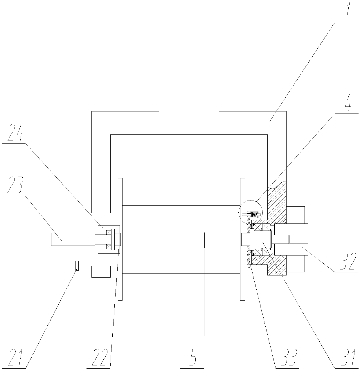
[0019] Such as figure 1 , figure 2 As shown, the wire-releasing cradle includes a cradle 1, a left support device, a right support device and a limit device 4;

[0020] The left supporting device is arranged on the left arm of the cradle 1 and includes a cylinder 23 and a left supporting shaft 22;

[0021] The air cylinder 23 is provided with an air nozzle 21, and the cylinder 23 is fixedly installed on the left arm of the cradle 1, and the piston end is fixedly connected with a fixed block 24, and the fixed block 24 is slid left and right and arranged on the left arm of the cradle 1, and the left support The axis of the shaft 22 is arranged left and right, and is rotatably mounted on the fixed block 24;

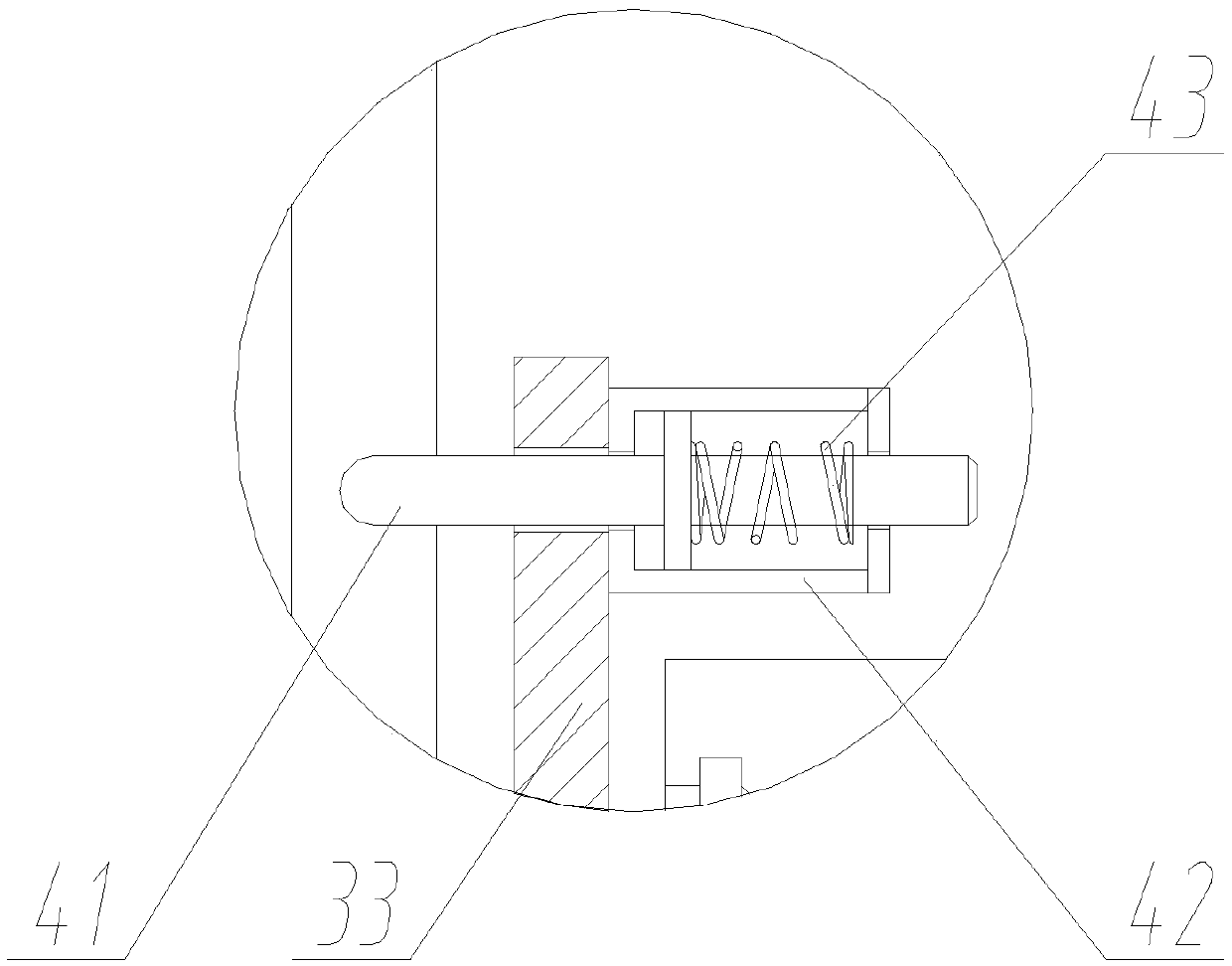
[0022] The right supporting device is arranged on the right arm of the cradle 1 and includes a fixed plate 33, a magnetic powder brake 32 and a right supporting shaft...


PUM


Abstract

The invention discloses a coil tool unwinding cradle. The coil tool unwinding cradle comprises a left supporting device, a right supporting device and a limiting device. The left supporting device isarranged on a left arm of a cradle, and comprises an air cylinder and a left supporting shaft. The piston end of the air cylinder is fixedly connected with a fixing block, the fixing block is arrangedon a left arm of the cradle in a left-and-right slide mode, and the left supporting shaft is installed on the fixing block in a rotating mode. The right supporting device is arranged on a right arm of the cradle, and comprises a fixing plate, a magnetic powder brake and a right supporting shaft. The middle of the right supporting shaft is installed on a right arm of the cradle in a rotating mode,the left portion of the right supporting shaft stretches out of the right arm of the cradle and is located on the left side, the fixing plate is fixedly installed on the left portion of the right supporting shaft, and the right end of the right supporting shaft is connected with the magnetic powder brake. The limiting device is installed on the portion, close to the center, of the fixing plate, and comprises a sleeve, a compression spring and a locating rod. The axis of the right supporting shaft and the axis of the left supporting shaft are consistent, and a coil tool is arranged between theright supporting shaft and the left supporting shaft in a clamped mode. By the adoption of the coil tool unwinding cradle, unwinding operation of the coil tool is achieved, rapid installation of thecoil tool is achieved, unwinding tension adjustment is facilitated, and the efficiency is higher.

Description

technical field [0001] The invention relates to the field of wire processing, in particular to a wire-discharging cradle. Background technique [0002] In the process of wire processing, it is necessary to use a large number of wire defense devices. For example, in the processing of transposed wires, it is necessary to stabilize the wire defense of a single raw material wire to prevent the phenomenon of wire clamping. [0003] The pay-off cradle in the existing pay-off device includes a left cradle arm and a right cradle arm, which mainly erects the tray on the left and right arms of the pay-off cradle, and the tray itself has mounting holes and positioning holes, which are realized through the installation holes. To fix the disk, the position of the disk is realized through the positioning hole. When installing the disk, it is necessary to manually align the installation hole first, and then align the positioning hole. Because the positioning hole is small, it is very incon...

Claims


Application Information

Patent Timeline
Patent Type & Authority Applications(China)
IPC IPC(8): B65H59/04B65H49/30B65H49/36
CPCB65H59/04B65H49/30B65H49/36B65H2701/341
Inventor 薛家祥
Owner 徐州楚光能源科技有限公司
Why Eureka
Try Eureka