Locking Mechanism in Batch Grabbing Device for Special Gas Cylinders

A special gas and grabbing device technology, applied in the field of machinery, can solve the problems of poor safety and high labor intensity, and achieve the effects of compact structure, improved stability and high practical value

Active Publication Date: 2020-06-16
浙江英德赛半导体材料股份有限公司
View PDF7 Cites 1 Cited by
  • Summary
  • Abstract
  • Description
  • Claims
  • Application Information

AI Technical Summary

Problems solved by technology

[0003] The existing handling operations are usually manual operations, which are labor-intensive and less safe

Method used


Image

  • Locking Mechanism in Batch Grabbing Device for Special Gas Cylinders
  • Locking Mechanism in Batch Grabbing Device for Special Gas Cylinders

Examples


Embodiment Construction

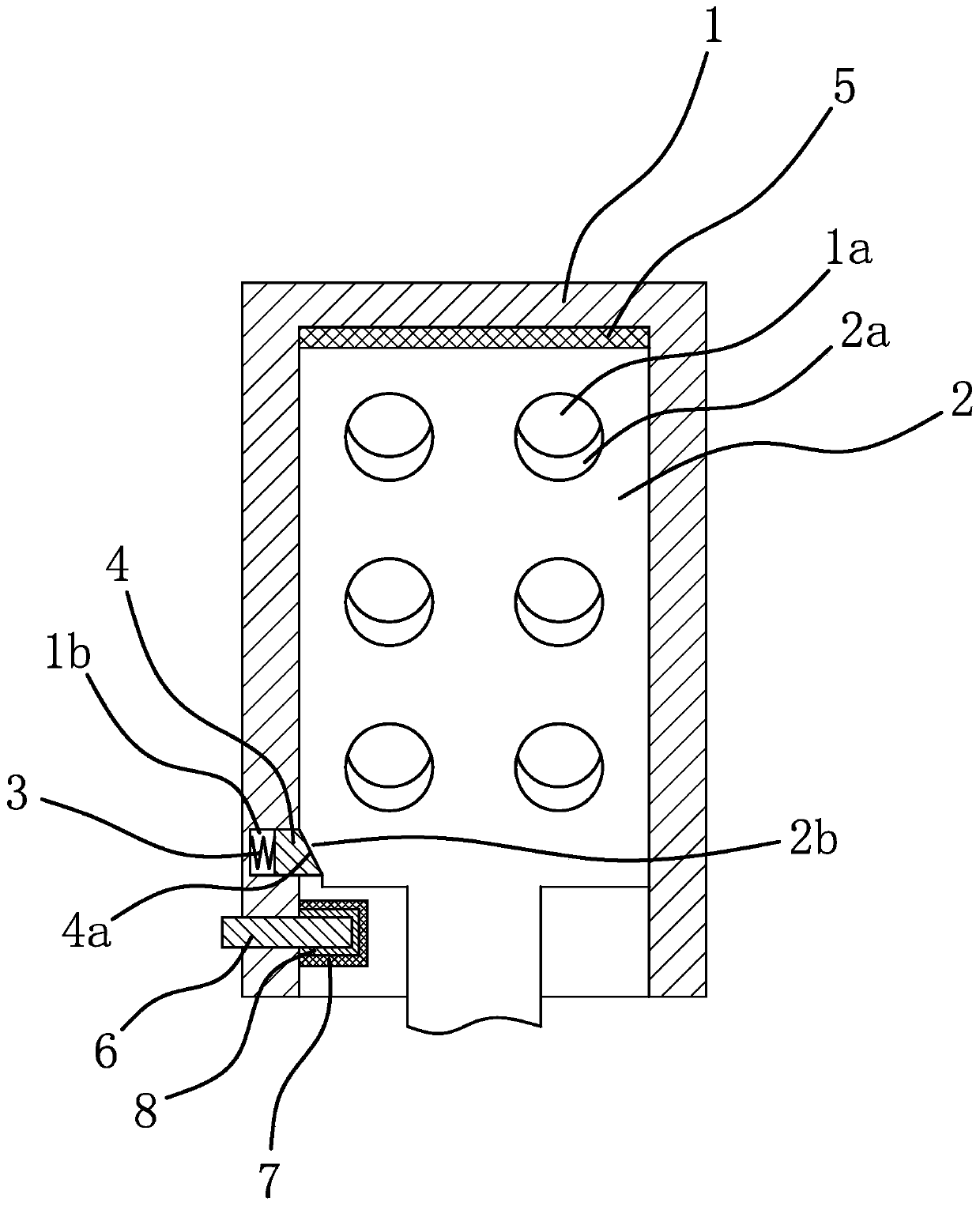
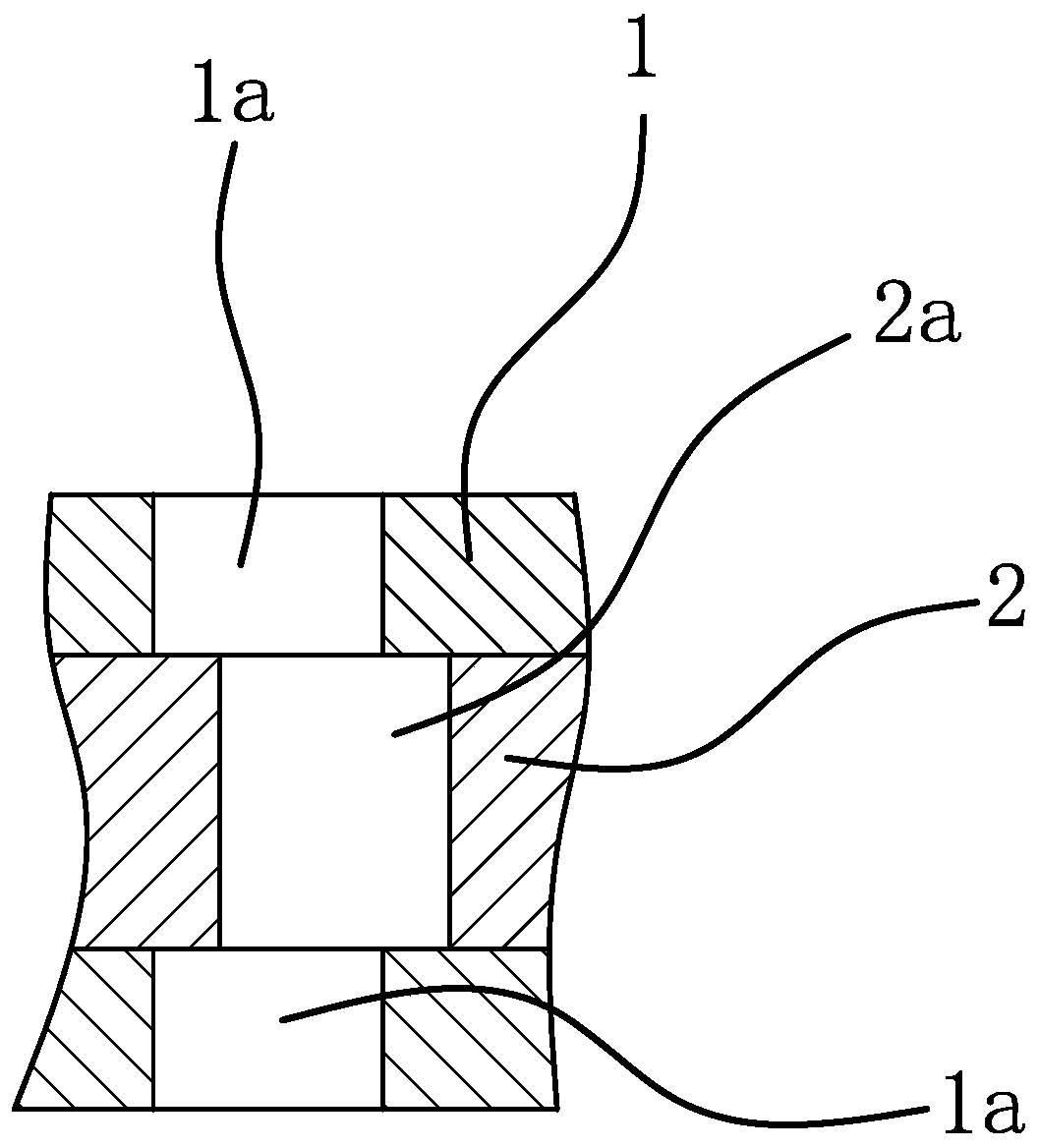
[0033] Such as figure 1 As shown, the batch grabbing device for special gas steel cylinders includes a fixed plate 1 and a movable plate 2. The interior of the fixed plate 1 is a cavity and there are a number of positioning holes-1a running through both sides of the fixed plate 1. The movable plate 2. Located in the fixed plate 1 and the movable plate 2 has a number of positioning holes 2a passing through its two sides. The above-mentioned positioning holes 1a and positioning holes 2a are set in one-to-one correspondence. When the movable plate 2 moves relative to the fixed plate 1, it is positioned Hole two 2a can be dislocated with positioning hole one 1a.

[0034] Such as figure 1 and figure 2 As shown, the locking mechanism in the special gas cylinder batch grabbing device is arranged between the fixed plate 1 and the movable plate 2, including a locking hole 1b recessed inside the fixed plate 1, and the locking hole 1b has a spring 3 and a Lock pin 4, the inner ends o...


PUM


Abstract

The invention provides a locking mechanism in a special gas steel bottle batch type grabbing device and belongs to the technical field of machinery. By means of the locking mechanism in the special gas steel bottle batch type grabbing device, the problem of poor stability existing in the prior art is solved. The locking mechanism in the special gas steel bottle batch type grabbing device is arranged between a fixed plate and a moving plate and comprises a locking hole concaved in the inner side of the fixed plate, the locking hole is internally provided with a spring and a locking pin, the spring and the inner end of the locking pin are both located inside the locking hole, the outer end of the locking pin stretches out of the locking hole, the side portion of the moving plate is providedwith an inclined force acting surface, and under the pushing squeezing effect of the locking pin, the moving plate has a tendency to move into the fixed plate and makes first positioning holes be in one-to-one correspondence with second positioning holes. The locking mechanism in the special gas steel bottle batch type grabbing device has high stability.

Description

technical field [0001] The invention belongs to the technical field of machinery, and relates to a locking mechanism in a batch grabbing device for special gas cylinders. Background technique [0002] Steel cylinders are used for stable storage of special gases, and the steel cylinders need to be transported during the use of special gases. [0003] The existing handling operation is usually manual operation, which has high labor intensity and relatively poor safety. Contents of the invention [0004] The object of the present invention is to solve the above-mentioned problems in the prior art, and provide a locking mechanism in a batch grabbing device for special gas cylinders with high stability and compact structure. [0005] The purpose of the present invention can be achieved through the following technical solutions: [0006] A locking mechanism in a batch-type grabbing device for special gas cylinders. The batch-type grabbing device for special gas cylinders inclu...

Claims


Application Information

Patent Timeline
Patent Type & Authority Patents(China)
IPC IPC(8): B66C1/10
CPCB66C1/10
Inventor 王龙张清峰杨康林新旺鄢芝勇李杰丁高松沈佳跃董夏梦
Owner 浙江英德赛半导体材料股份有限公司
Why Eureka
Try Eureka