
Measurement and quick vacuumizing method and device for inner cavity vacuum degree of component with tubule

A vacuum degree and vacuum pumping technology, which is applied to measuring devices, pump devices, vacuum gauges, etc., can solve problems such as low production efficiency, long vacuuming time, and large difference in vacuum degree, and achieve the effect of improving production efficiency

Inactive Publication Date: 2019-04-09
GUIZHOU HONGLIN MACHINERY
View PDF5 Cites 0 Cited by
  • Summary
  • Abstract
  • Description
  • Claims
  • Application Information

AI Technical Summary

Problems solved by technology

Due to the length of the thin tube is too long, the vacuum degree difference between the end of the thin tube and the inner cavity of the component is relatively large, about two orders of magnitude, so the actual inner cavity vacuum degree is not truly displayed
Moreover, the vacuuming device uses a diffusion pump unit to directly evacuate the components, which takes a long time to evacuate and the production efficiency is very low

Method used


Image

  • Measurement and quick vacuumizing method and device for inner cavity vacuum degree of component with tubule
  • Measurement and quick vacuumizing method and device for inner cavity vacuum degree of component with tubule

Examples


Embodiment 1

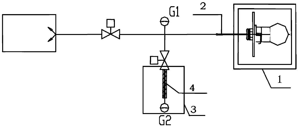
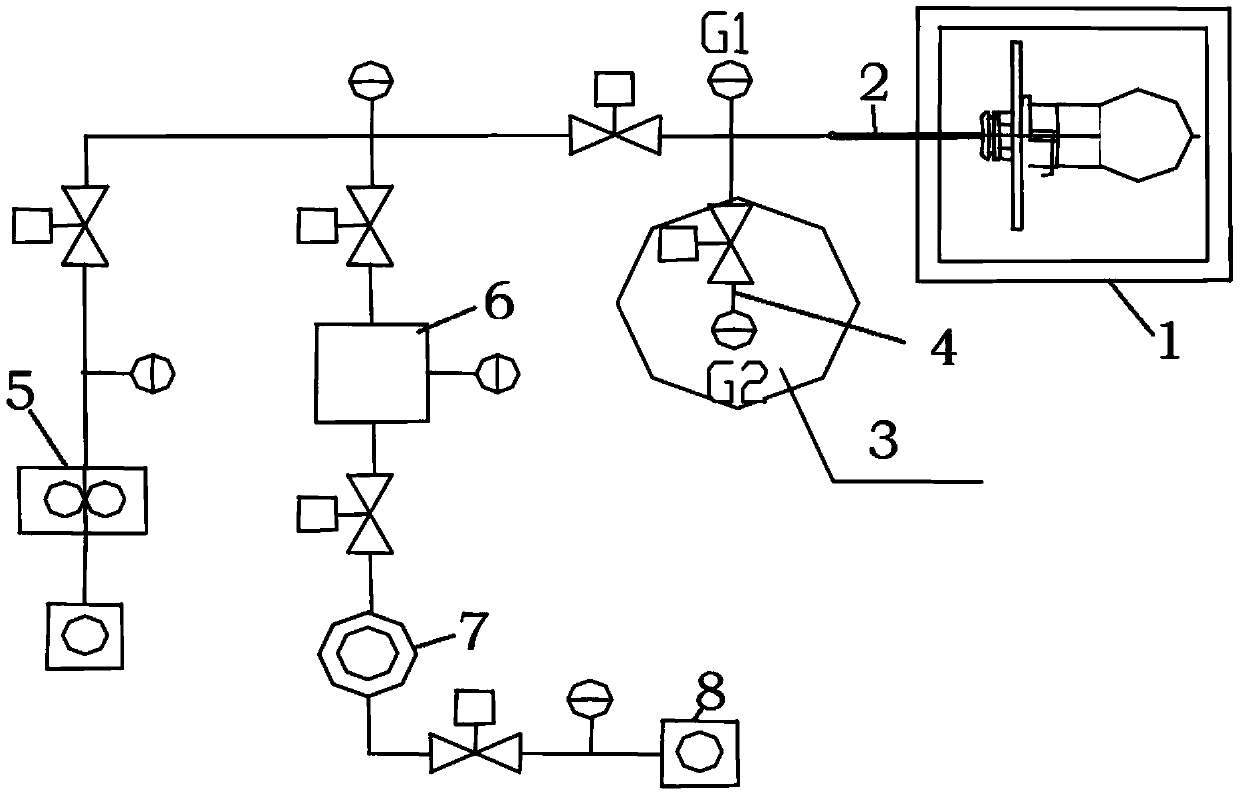
[0017] Embodiment 1 of the present invention: a device for measuring and quickly vacuuming the inner cavity of a thin tube assembly, such as figure 1 As shown, it includes the analog part 3 connected with the thin tube 2 with the thin tube assembly 1, the simulated thin tube 4 of the simulated part 3 has the same inner diameter and length as the thin tube 2, and the vacuum gauge G2 is connected to the end of the simulated thin tube 4, and the thin tube 2 and the simulated thin tube 4 are connected to a vacuum unit, and a vacuum gauge G1 is also connected to the pipeline. For the analog thin tube 4 whose inner diameter is too small to be directly connected to the vacuum gauge, the outer diameter is enlarged so that the analog part is directly sealed and connected with the vacuum gauge G2.

[0018] Such as figure 2 As shown, the thin tube 2 with the thin tube assembly 1 is also connected to the Roots pump unit 5 and the counter vacuum station 6 respectively. The hedging vacuu...

Embodiment 2

[0022] Embodiment 2 of the present invention: a device for measuring and quickly vacuuming the inner cavity of a thin tube assembly, such as figure 1 As shown, it includes a dummy part 3 connected to the thin tube 2 with a thin tube assembly 1, the simulated thin tube 4 of the simulated part 3 has the same inner diameter and length as the thin tube 2, and a vacuum gauge G2 is connected to the end of the simulated thin tube 4.

[0023] When in use, the front section of the narrow tube 2 with the thin tube assembly 1 is connected to the analog part 3 through a three-way valve. Since the simulated thin tube 4 of the simulated part 3 has the same inner diameter and length as the thin tube 2, a vacuum gauge G2 is connected to the end of the simulated thin tube 4 , the vacuum degree of the inner cavity of the assembly with thin tube 1 can be simulated by the vacuum gauge G2.


PUM

PropertyMeasurementUnit
lengthaaaaaaaaaa

Abstract

The invention discloses a measurement and quick vacuumizing method and device for the inner cavity vacuum degree of a component with a tubule. The device is characterized in that the front section ofthe tubule (2) of a component (1) with the tubule is connected with a simulation element (3) through a three-way valve; the simulation tubule (4) of the simulation element (3) has the consistent internal diameter and length with the tubule (2); the tail end of the simulation tubule (4) is connected with a vacuum gauge (G2); and the vacuum gauge (G2) is used for simulating the inner cavity vacuum degree of the component (1) with the tubule. The device has the advantages that the vacuum degree of the component with the tubule can be truly reflected and vacuumizing time is greatly shortened.

Description

technical field [0001] The invention relates to the technical field of measuring and vacuuming the inner cavity of a component with thin tubes, in particular to a method and a device for measuring the vacuum degree and rapidly evacuating the inner cavity of a component with thin tubes. Background technique [0002] The assembly with thin tube has the following particularities: the inner diameter of the thin tube is within φ1.5 mm, the length is more than 50 mm, and the assembly has a certain volume of blind cavity. In the existing vacuuming device, a process joint is usually connected to the end of the narrow tube of the component, and the joint is connected with the vacuuming device; the vacuum gauge device is installed on the pipeline connected to the end of the thin tube. Due to the long length of the capillary, the difference between the end of the capillary and the inner cavity of the component is relatively large, about two orders of magnitude, so the actual vacuum of ...

Claims


Application Information

Patent Timeline
Patent Type & Authority Applications(China)
IPC IPC(8): G01L21/00F04B41/06
CPCF04B41/06G01L21/00
Inventor 周湘
Owner GUIZHOU HONGLIN MACHINERY
Learn More