
Method and device for controlling short-circuit current of substation, storage medium and processor

A technology of short-circuit current and control method, applied in circuit devices, panel/switch station circuit devices, AC network circuits, etc., can solve the problem of substation current cannot be effectively controlled, improve safety and flexibility, and ensure reliable power supply sexual effect

Active Publication Date: 2019-04-09
ELECTRIC POWER RESEARCH INSTITUTE OF STATE GRID NINGXIA ELECTRIC POWER COMPANY
View PDF4 Cites 4 Cited by
  • Summary
  • Abstract
  • Description
  • Claims
  • Application Information

AI Technical Summary

Problems solved by technology

[0006] The main purpose of the present invention is to provide a control method, device, storage medium and processor for the short-circuit current of a substation, so as to at least solve the technical problem that the current of the substation cannot be effectively controlled

Method used


Image

  • Method and device for controlling short-circuit current of substation, storage medium and processor
  • Method and device for controlling short-circuit current of substation, storage medium and processor
  • Method and device for controlling short-circuit current of substation, storage medium and processor

Examples


Embodiment 1

[0030] The embodiment of the present invention provides a method for controlling the short-circuit current of a substation.

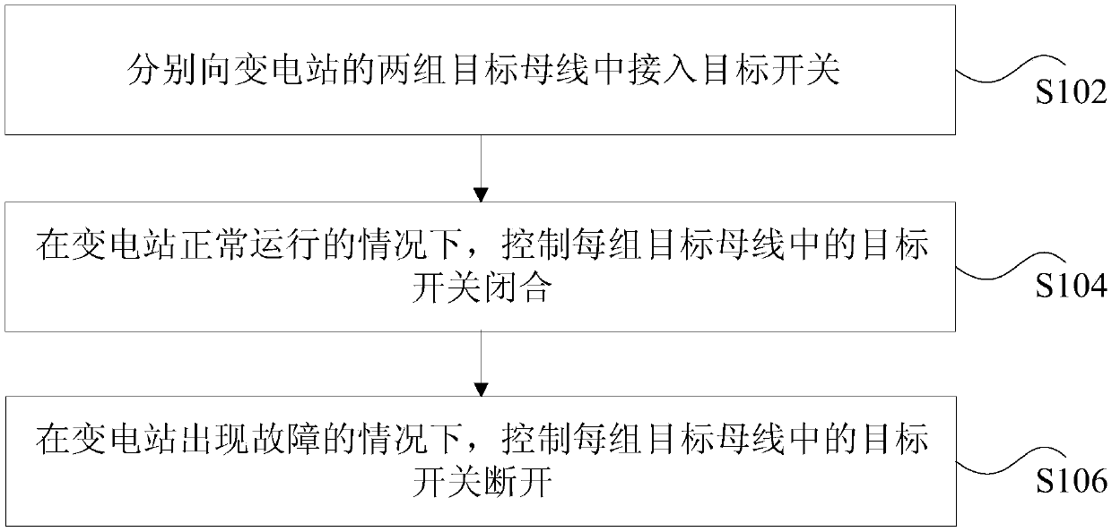
[0031] figure 1 It is a flowchart of a method for controlling short-circuit current of a substation according to an embodiment of the present invention. Such as figure 1 As shown, the method includes the following steps:

[0032] Step S102, connecting target switches to two groups of target buses of the substation respectively.

[0033] In the technical solution provided by the above step S102 of the present invention, the target switches are respectively connected to the two groups of target buses of the substation.

[0034]In this embodiment, the substation is a substation to be subjected to current control, for example, it may be a 2 / 3 wiring substation. The substation includes two sets of busbars, and the two sets of busbars can run in parallel, that is, the two sets of busbars can run simultaneously. The target switch in this embodiment can be...

Embodiment 3

[0066] The technical solution of the present invention will be described below in combination with preferred implementation modes. Specifically, the substation is a 3 / 2 wiring substation, and the target switch is a fast switch for example.

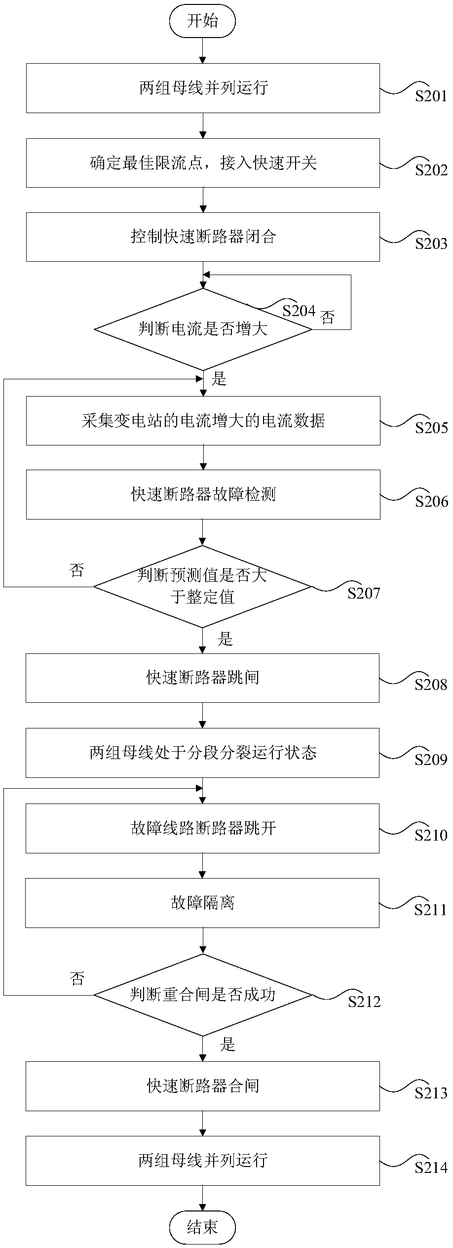
[0067] figure 2 It is a flow chart of a method for applying current limiting in a 3 / 2 wiring substation to a fast switch according to an embodiment of the present invention. Such as figure 2 As shown, the method includes the following steps:

[0068] In step S201, two sets of busbars run in parallel.

[0069] The two groups of busbars of the substation in this embodiment may initially be in parallel operation state.

[0070] Step S202, determine the optimal current limiting point, and switch on the fast switch.

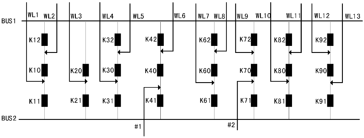
[0071] Calculate the optimal current limiting point of the bus in the 3 / 2 connection substation, and use the optimal current limiting point as the segment point of the two groups of buses to connect to the fast switch. Amon...

Embodiment 4

[0126] The embodiment of the present invention also provides a storage medium. The storage medium includes a stored program, wherein when the program is running, the device where the storage medium is located is controlled to execute the method for controlling the short-circuit current of the substation in the embodiment of the present invention.


PUM


Abstract

The invention discloses a method and device for controlling short-circuit current of a substation, a storage medium and a processor. The method includes the following steps: accessing target switchesto two sets of target buses of the substation respectively; in the case of normal operation of the substation, controlling the target switch in each set of target buses to be closed, wherein the closed target switches cause the two sets of target buses to be in a simultaneous operation state; and in the case that the substation fails, controlling the target switch in each set of target buses to bedisconnected, wherein the disconnected target switches cause the two sets of target buses to be converted from the simultaneous operation state to a segmented split operation state, and in the segmented split operation state, each set of target buses is divided into two sections of sub-buses, so that the substation performs split operation, and the current of the substation that performs split operation is lower than the current of the substation that fails. According to the scheme of the invention, the technical effect of effectively controlling the current of the substation can be achieved.

Description

technical field [0001] The present invention relates to the field of current control, in particular to a control method, device, storage medium and processor for short-circuit current of a substation. Background technique [0002] At present, with the rapid development of the power system, large-scale power plants have been put into operation one after another, the installed capacity has increased, the power grid has become increasingly connected, the structure has been strengthened, and the number of ring networks has increased, resulting in an increase in the short-circuit current of the system year by year. interrupting capacity). Exceeding the short-circuit current of the system is a serious hidden danger to the safe operation of the power grid. If the circuit breaker cannot extinguish the arc to break the short-circuit current, it may cause an explosion of the circuit breaker, which may cause a short circuit of the busbar or cause a systemic accident. [0003] The curr...

Claims


Application Information

Patent Timeline
Patent Type & Authority Applications(China)
IPC IPC(8): H02B1/24H02J3/00
CPCH02B1/24H02J3/0073
Inventor 艾绍贵马莉黄欣黄永宁摆存曦樊益平张爽田蓓张汉花焦龙任勇梁剑顾雨嘉吴玫蓉
Owner ELECTRIC POWER RESEARCH INSTITUTE OF STATE GRID NINGXIA ELECTRIC POWER COMPANY
Learn More