A flexible interconnection system between low-voltage buses in a substation and its control method

A low-voltage busbar and interconnection system technology, which is applied in the field of flexible interconnection system between low-voltage busbars in substations and its control field, can solve problems not involving flexible interconnection of distribution busbars, improve power quality, reduce basic capacity, and increase local consumption capacity Effect

Active Publication Date: 2019-07-30
SHANGHAI JIAOTONG UNIV
View PDF5 Cites 2 Cited by
  • Summary
  • Abstract
  • Description
  • Claims
  • Application Information

AI Technical Summary

Problems solved by technology

[0007] With a large number of new energy sources connected to the distribution network and users' demand for high power quality, the traditional bus tie switch can no longer meet the requirements in terms of control capability and response speed. It is necessary to implement multi-bus flexible interconnection to realize the power flow between buses. and other flexible interactions
[0008] After retrieval, the article "Increasing distributed generation penetration using soft normally-open points" (IEEE Power and Energy Society General Meeting, 2010) published by Jeffrey M. Bloemink et al. proposed to use SNOP (soft normally open switch) to replace the traditional low-voltage distribution network feeder The connection switch in the distribution network realizes the flexible interconnection scheme of the feeder end of the distribution network, but it does not involve the design of the flexible interconnection scheme for the distribution busbar. Since the two are different according to the installation position, there are differences in design and control.

Method used


Image

  • A flexible interconnection system between low-voltage buses in a substation and its control method
  • A flexible interconnection system between low-voltage buses in a substation and its control method
  • A flexible interconnection system between low-voltage buses in a substation and its control method

Examples


Embodiment Construction

[0040] The present invention will be described in detail below in conjunction with specific embodiments. The following examples will help those skilled in the art to further understand the present invention, but do not limit the present invention in any form. It should be pointed out that for those of ordinary skill in the art, a number of modifications and improvements can be made without departing from the concept of the present invention. These all belong to the protection scope of the present invention.

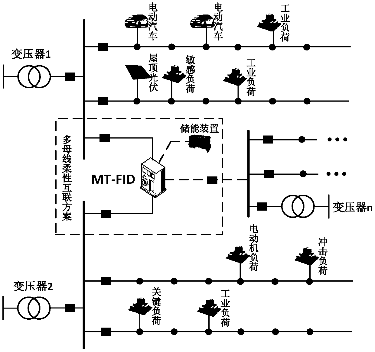
[0041] Such as figure 1 As shown, the schematic diagram of the application scheme of the flexible interconnection system of the multi-port flexible interconnector (MT-FID) of the present invention on the outlet side busbar of the distribution transformer includes: a plurality of transformers and a multi-port flexible interconnect In the substation, the multi-port flexible interconnector is connected to each adjacent transformer outlet bus bar to realize multi-bus flexible ...


PUM


Abstract

The invention provides a flexible interconnection system between transformer station low voltage buses and a control method thereof; the system comprises a plurality of transformers and a multi-port flexible interconnection device; the transformers are arranged in the system transformer station; the adjacent transformer outlet buses are connected with the multi-port flexible interconnection device so as to realize multi-bus flexible interconnection. The system aims at the plurality of adjacent buses on the transformer outlet side in the same transformer station, and uses the multi-port flexible interconnection device to replace a buscouple switch, thus realizing the multi-bus flexible interconnection; the power electronic equipment controllability is employed to realize multi-bus trend interactions. The system and method can realize multi-bus parallel operations without increasing short circuit currents, thus improving the new energy local absorptive ability, improving the inter-bus load balancing level, improving the transformer load rate, reducing the transformer basic capacity, improving the power supply reliability, and improving the electric energy quality through proper control.

Description

Technical field [0001] The invention relates to the technical fields of power distribution and power electronics in a power system, in particular to a flexible interconnection system between low-voltage buses of a substation and a control method thereof. Background technique [0002] In the traditional distribution network, the outlet bus bars of different transformers in the same substation are interconnected through bus tie switches, which have the following functions: [0003] 1. Two busbars are operated in parallel (connected to the grid) or de-sequenced (connected to the grid); [0004] 2. In the parallel operation of busbars, when one of the busbars and its line fails, the protection action will separate the bus tie switch in time to ensure the normal power supply of the other busbar and reduce the power outage range; [0005] 3. During the switching operation, close the bus tie switch to perform equipotential non-stop operation; [0006] 4. When the circuit breaker is faulty, th...

Claims


Application Information

Patent Timeline
Patent Type & Authority Patents(China)
IPC IPC(8): H02J3/38H02J3/06
CPCH02J3/06H02J3/38
Inventor 张建文周剑桥蔡旭施刚
Owner SHANGHAI JIAOTONG UNIV
Why Eureka
Try Eureka