
Protection circuit, upper bridge driver chip and IPM module

A technology for protecting circuits and driving modules, applied in the electronic field, can solve the problems of not being able to protect the safety of the upper bridge power device in time, and the failure of the upper bridge driving circuit to be closed in time, so as to achieve the effect of providing reliability and avoiding the overcurrent state

Active Publication Date: 2019-04-09
HISENSE HOME APPLIANCES GRP CO LTD +1
View PDF9 Cites 6 Cited by
  • Summary
  • Abstract
  • Description
  • Claims
  • Application Information

AI Technical Summary

Problems solved by technology

Due to the cost factor, an external upper bridge overcurrent protection circuit is generally not installed in the application, which leads to the fact that when the upper bridge overcurrent occurs, the upper bridge drive circuit cannot be turned off in time, so that the safety of the upper bridge power device cannot be protected in time

Method used


Image

  • Protection circuit, upper bridge driver chip and IPM module
  • Protection circuit, upper bridge driver chip and IPM module
  • Protection circuit, upper bridge driver chip and IPM module

Examples


Embodiment 1

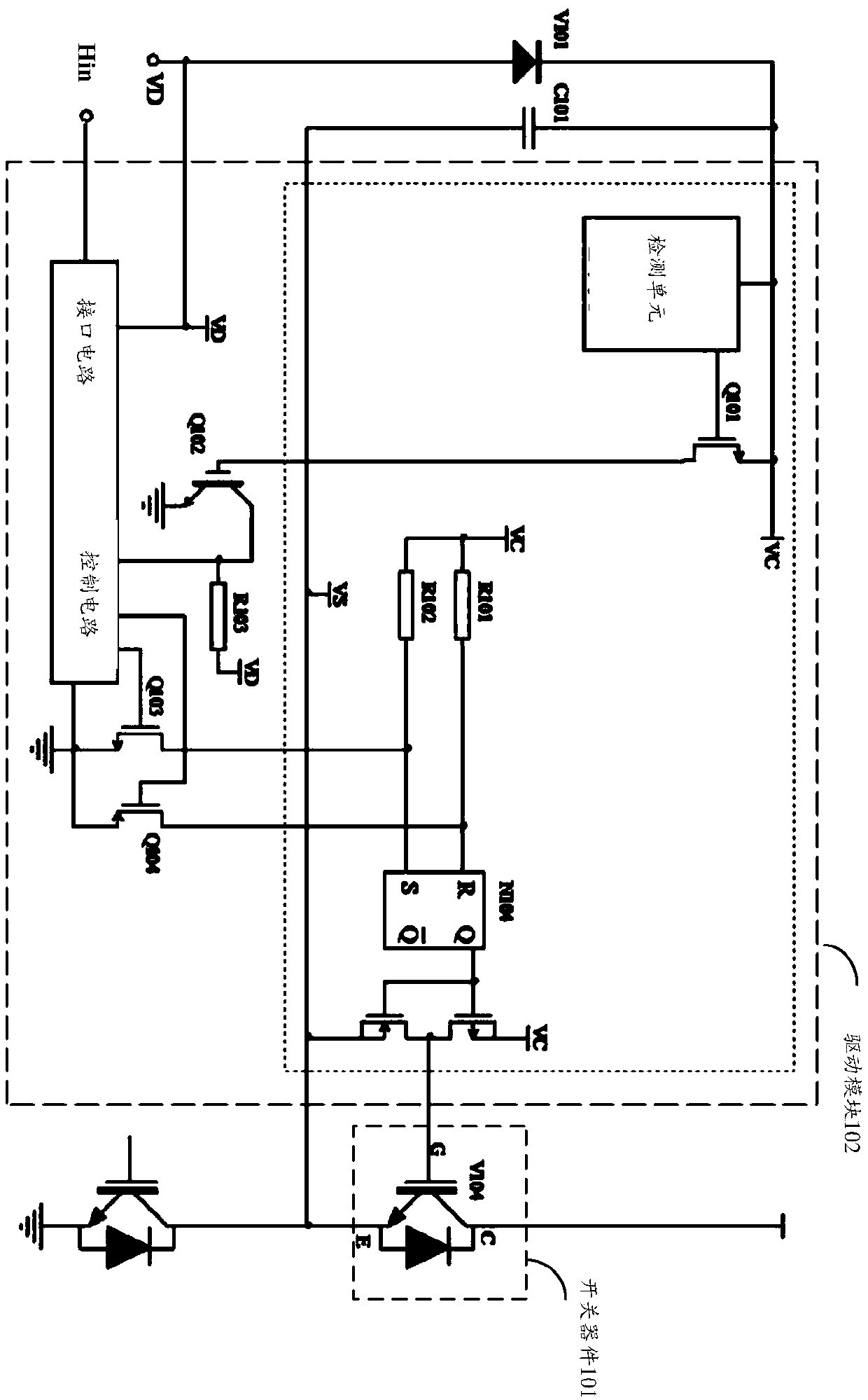
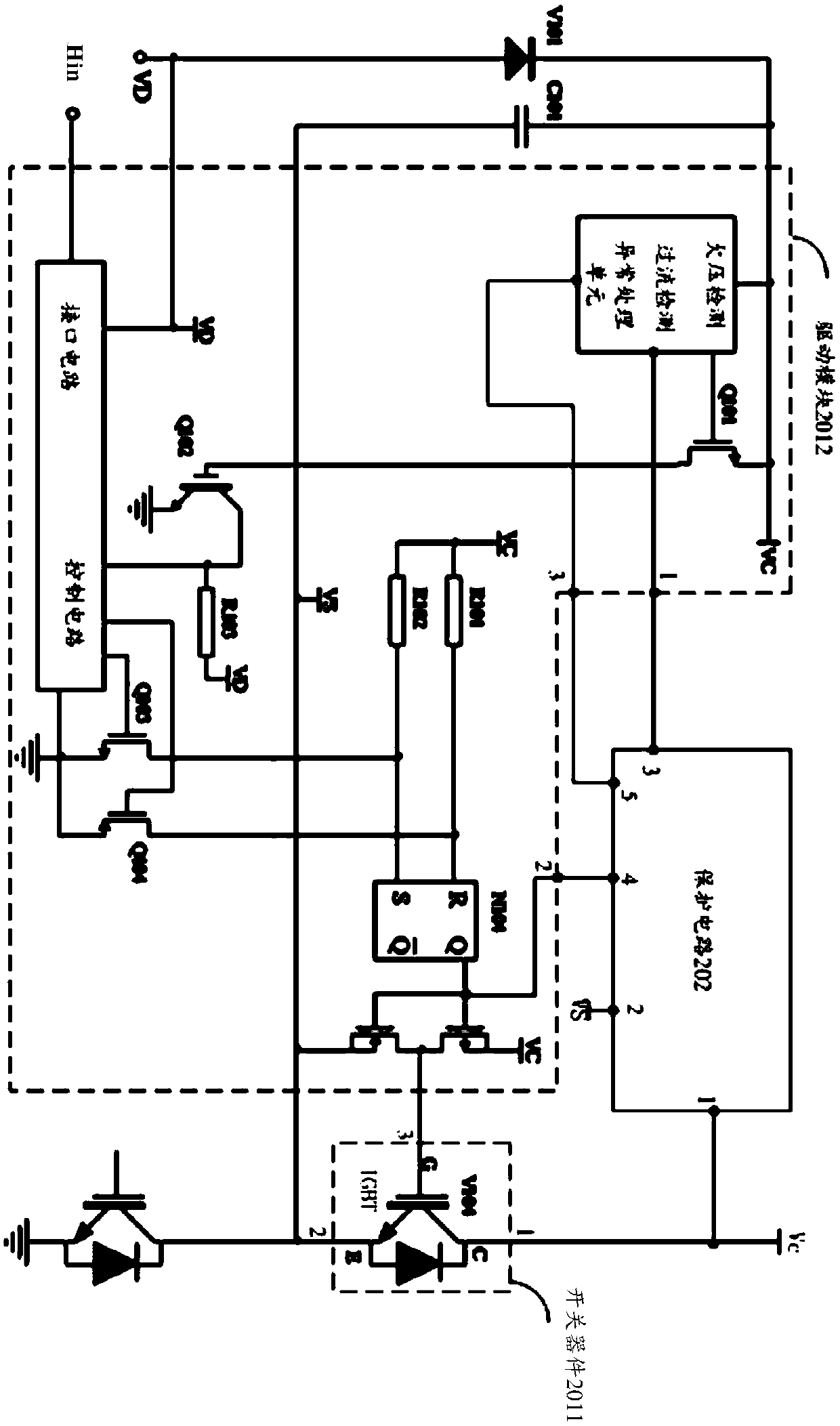
[0026] Based on the foregoing principles of the invention, embodiments of the present invention provide a protection circuit, which is applied to control an upper bridge drive circuit. Such as image 3 What is shown is a schematic diagram of the circuit structure of an upper bridge driving circuit and a protection circuit provided by the present invention, where the upper bridge driving circuit 201 includes a power switch device 2011 and a driving module 2012. The first end of the power switch device 2011 is connected to the power source, the second end is connected to the second end of the power switch device 2011 in the upper bridge, and the third end of the power switch device 2011 is connected to the driving module 2012. The driving module 2012 is used to control the on / off between the first terminal and the second terminal of the power switch device 2011. Specifically, the structure of the power switching device 2011 can refer to figure 2 The structure of the medium power...

Embodiment 2

[0050] The embodiment of the present invention also provides an upper bridge driving chip, such as Image 6 As shown, the upper bridge driving chip 30 includes a driving module 301, wherein the upper bridge driving circuit 30 further includes the protection circuit 202 as provided in the first embodiment.

[0051] For the description of the driving module 301, please refer to the corresponding description of the driving module 2012 in the first embodiment, which will not be repeated here.

Embodiment 3

[0053] The embodiment of the present invention also provides a driving chip including an upper bridge driving function, such as Figure 7 As shown, the driver chip 40 including the upper bridge driving function includes a driving module 401, and the driver chip 40 including the upper bridge driving function further includes the protection circuit 202 as provided in the first embodiment.

[0054] Specifically, the driving chip 40 including the upper bridge driving function may be a driving circuit chip such as an upper and lower bridge circuit, an H bridge circuit, and the like.

[0055] In addition, the description of the driving module 401 can refer to the corresponding description of the driving module 2012 in the first embodiment, which is not repeated here.


PUM


Abstract

The invention provides a protection circuit, an upper bridge driver chip and an IPM module, and relates to the technical field of electronics. The embodiment of the invention can detect the overcurrent in the upper bridge driving circuit in time, and turn off the upper bridge driving circuit through the control circuit in time after detecting the overcurrent to avoid the continuous overcurrent state of the upper bridge power switching device, thereby protecting the upper bridge power device and improving the reliability of the upper bridge driving circuit. The first end of the protection circuit is connected to the first end of the power switching device, the second end of the protection circuit is connected to the second end of the power switching device, the third end of the protection circuit is connected to the first end of the driving module, and the protection circuit is used for outputting a first level signal by the third end of the protection circuit when the voltage between the first end and the second end of the protection circuit is greater than the threshold voltage, so that the driving module receives the first level signal and then controls the upper bridge power switching device to be turned off. The invention is applied to control the driving of the upper bridge power switching device and its protection circuit.

Description

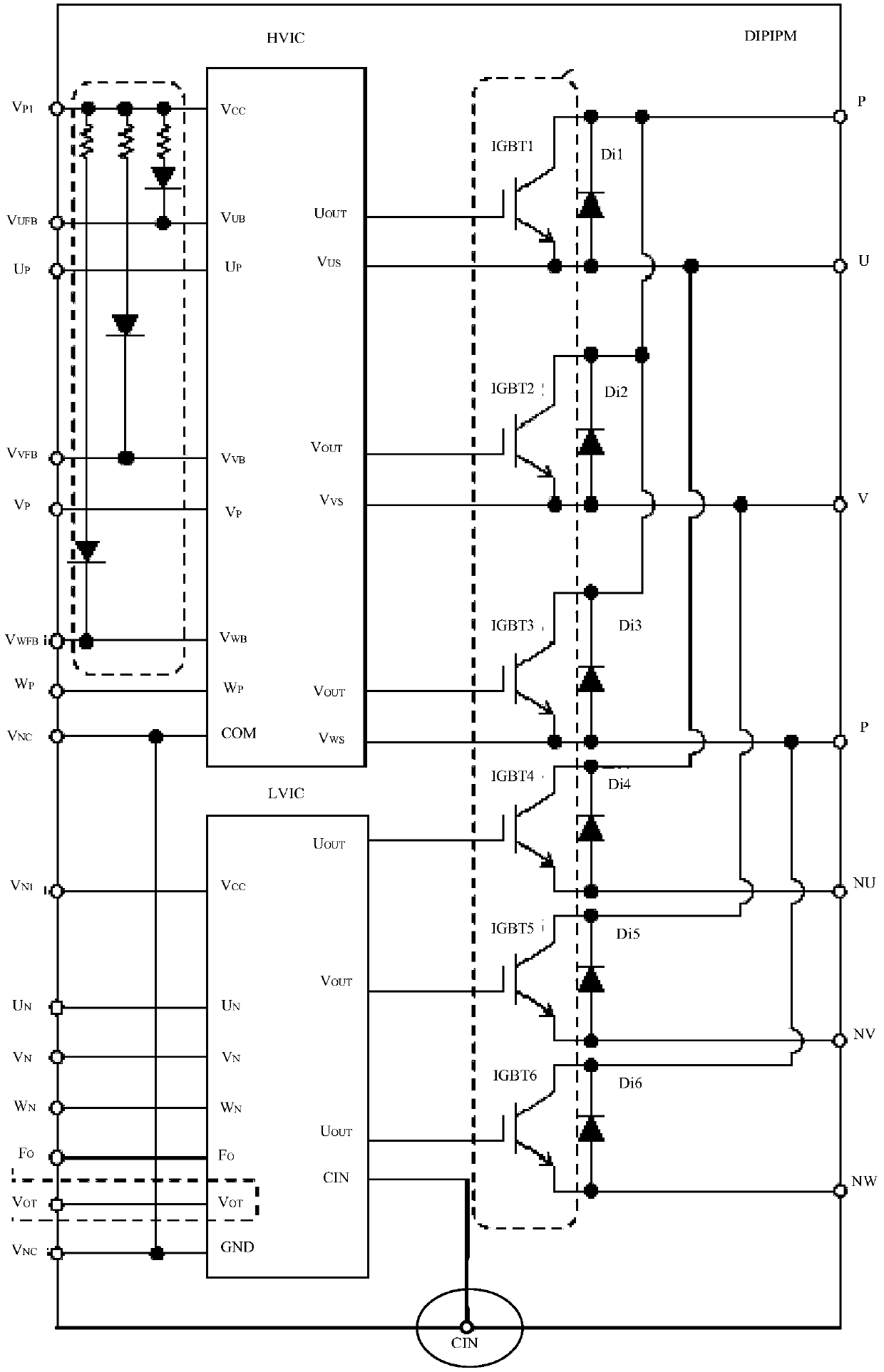
Technical field [0001] The invention relates to the field of electronic technology, in particular to a protection circuit, an upper bridge drive chip and an IPM module. Background technique [0002] At present, brushless DC motors are used in more and more electrical equipment. As a very important part of the DC brushless motor, the drive circuit has an important impact on the running performance of the DC brushless motor. Such as figure 1 As shown, it is a schematic diagram of the circuit principle of an IPM module circuit in the prior art. The IPM module circuit includes 6 power switching devices IGBT (insulated gate bipolar transistor) (IGBT1-IGBT6 in the figure), 6 FRD (Fast recovery diode, fast recovery diode) (Di1-Di6 in the figure) and the upper Bridge control chip (HVIC in the picture), lower bridge control chip (LVIC in the picture). Among them, HVIC and LVIC are used from U P , V P , W P , U N , V N , W N The 6 ports receive 6 control signals, and pass U in the HVIC ...

Claims


Application Information

Patent Timeline
Patent Type & Authority Applications(China)
IPC IPC(8): H02H7/20H02H3/08
CPCH02H3/08H02H7/20
Inventor 王斌
Owner HISENSE HOME APPLIANCES GRP CO LTD
Learn More