Tunnel aerial rail-determination-type moving fire extinguishing system
A fire-extinguishing system and a fixed-orbit technology, which is applied in the field of a fixed-orbit mobile fire-extinguishing system in tunnels, can solve problems such as being limited by human skills and responses, limited application scope, unsuitable for extinguishing hydrocarbons, and electrical fires, etc. To achieve the effect of automatic inspection, avoid misoperation, and quickly and effectively extinguish the fire
- Summary
- Abstract
- Description
- Claims
- Application Information
AI Technical Summary
Problems solved by technology
Method used
Image
Examples
Embodiment 1
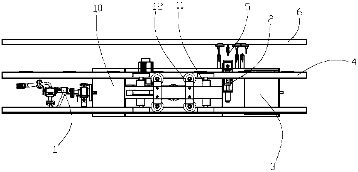
[0040] Embodiment 1: A mobile fire extinguishing system with rail fixed in the air for a tunnel, including 4 aerial track units, a fire extinguishing unit with a mobile trolley device, a high-pressure water supply unit, an external charging pile unit, and a fire alarm unit in the tunnel;
[0041] The fire extinguishing unit of the mobile car device includes a car device 10 and a fire extinguishing device 1, a water intake device 2, an internal charging device 3, a built-in rechargeable battery, and a control device arranged on the car device 10. The car device 10 is set on the aerial track 4 and can reciprocate along the air track 4;
[0042] The high-pressure water supply unit includes a plurality of water intakes 5 arranged along the aerial track, and each water intake 5 is connected to a high-pressure water supply pipe 6;
[0043] The external charging pile unit is arranged on the aerial track 4 .
[0044]The output end of the fire alarm unit in the tunnel is wirelessly co...
Embodiment 2
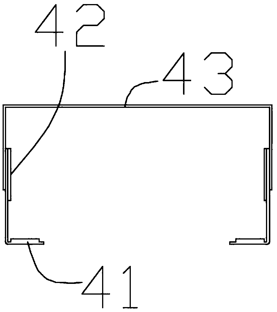
[0053] Example 2: figure 2 / 3 shows a preferred solution of the aerial track unit of the present invention, the aerial track unit includes a support track device 41, a side guide rail device 42, and an upper bearing cover device 43, corresponding to the above settings, the trolley device 10 is provided with support wheel set 11 and guide wheel set 12.
Embodiment 3
[0054] Example 3: Figure 4 / 5 / 6 shows a preferred solution of the centering device described in the present invention. The centering device includes an overtravel sensor 207, a centering sensor 201, a contact sensor 202, a centering sensor 204 is provided, and the positional relationship between the centering sensor 204 and the water intake 5 is consistent with the positional relationship between the centering sensor 201 and the water intake joint 19, and the rear end of the centering sensor 201 is provided with a contact sensor 203. The front end of the sensor 204 is provided with an overtravel sensor 208, and the distance between the overtravel sensor 207, the centering sensor 201, and the contact sensor 202 is smaller than the distance between the corresponding overtravel sensor 208, the centering sensor 204, and the contact sensor 203. Distance, wherein the difference between the distance between the overtravel sensor 208 and the centering sensor 204 and the distance betw...
PUM
 Abstract
Description
Claims
Application Information
 - R&D
- Intellectual Property
- Life Sciences
- Materials
- Tech Scout
- Unparalleled Data Quality
- Higher Quality Content
- 60% Fewer Hallucinations
Browse by: Latest US Patents, China's latest patents, Technical Efficacy Thesaurus, Application Domain, Technology Topic, Popular Technical Reports.
© 2025 PatSnap. All rights reserved.Legal|Privacy policy|Modern Slavery Act Transparency Statement|Sitemap|About US| Contact US: help@patsnap.com


