
Copper piece alignment device for power strip processing

A technology for aligning devices and copper parts, applied in the assembly/disassembly of contact parts, electrical components, conveyor objects, etc., can solve problems affecting connection stability, etc., and achieve the effect of complete process and accurate docking

Pending Publication Date: 2022-08-02
安徽突飞科技股份有限公司
View PDF0 Cites 0 Cited by
  • Summary
  • Abstract
  • Description
  • Claims
  • Application Information

AI Technical Summary

Problems solved by technology

[0005] The object of the present invention is to address the deficiencies of the prior art, to provide a device for aligning copper parts for plug-in processing, which sequentially transports the copper pieces forward through the lower hopper and the conveyor belt, and the transported copper pieces are first screened The component and the second screening component screen out the docking position of the copper sheet and continue to transmit it downward, and use the locking part and the alignment column to respectively check the convex part and the blind hole part of the copper sheet based on the locking part and the alignment column. Positioning, and finally use the docking unit to dock the two sets of copper sheets to achieve the accuracy of the docking and solve the existing problem that the inaccurate docking position affects the stability of the connection during the docking process

Method used


Image

  • Copper piece alignment device for power strip processing
  • Copper piece alignment device for power strip processing
  • Copper piece alignment device for power strip processing

Examples


Embodiment 1

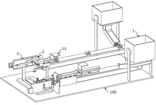
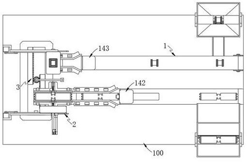
[0072] like Figure 1-2 As shown, an alignment device for copper parts for socket and row processing includes a workbench 100, and further includes:

[0073] A blanking unit 1, the blanking unit 1 for sequentially transporting the copper sheets downward is arranged at one end of the workbench 100;

[0074] The alignment unit 2 is used to connect the alignment unit 2 for aligning the position of the transmitted copper sheet with the blanking unit 1, and is located in the middle of the workbench 100;

[0075] The alignment unit 2 includes:

[0076] The alignment column assembly 21, which is used for locating the position of the copper sheet with the protrusions, is connected to the blanking unit 1, and is arranged on one side of the workbench 100; and

[0077] The hole alignment assembly 22, which is used for locating the position of the copper sheet with blind holes, is connected to the blanking unit 1, and is arranged on the other side of the workbench 100;

[0078] The doc...

Embodiment 2

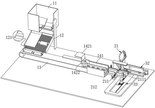
[0146] like Figure 3-4 , Image 6 As shown, the same or corresponding components as those in the first embodiment are given the corresponding reference numerals as in the first embodiment. For the sake of brevity, only the points of difference from the first embodiment are described below. The difference between the second embodiment and the first embodiment is:

[0147] further, as Figure 3-4 As shown, the first screening unit 142 includes:

[0148] a first mounting seat 1421, the first mounting seat 1421 is arranged on the workbench 100;

[0149] an intercepting plate 1422, the intercepting plate 1422 is arranged on the first installation;

[0150] an adsorption plate 1423, the adsorption plate 1423 is connected with the intercepting plate 1422, and is arranged on one side of the first mounting seat 1421;

[0151] When the intercepting plate 1422 blocks the copper sheet from falling into the conveyor belt 13 from the lower hopper 11, the side is placed on the conveyor...

Embodiment 3

[0162] like Figure 4 As shown, the same or corresponding components as those in the first embodiment are given the corresponding reference numerals as in the first embodiment. For the sake of brevity, only the points of difference from the first embodiment are described below. The difference between the first embodiment and the first embodiment is:

[0163] The first fixing mechanism 212 includes:

[0164] a first clamping plate 2121, the first clamping plate 2121 is elastically arranged on both sides of the first receiving plate 2111;

[0165] a first pressing plate 2122, the first pressing plate 2122 is slidably connected to the first clamping plate 2121;

[0166] The pushing device pushes forward, and drives the elastic piece elastically connected between the first clamping plate 2121 and the pushing device to squeeze the copper sheet. The outer part of the first clamping plate 2121 after the position is fixed is provided with a casing, which is pushed by the pushing dev...


PUM


Abstract

The invention provides a copper piece alignment device for power strip processing, which comprises a working table, and further comprises a blanking unit used for sequentially conveying copper sheets downwards and arranged at one end of the working table; the alignment unit used for aligning the positions of the conveyed copper sheets is connected with the discharging unit, the alignment unit is arranged on one side of the workbench, the copper sheets are conveyed forwards in sequence through a discharging hopper and a conveying belt, the butt joint positions of the conveyed copper sheets are screened out through a first screening assembly and a second screening assembly, and the copper sheets continue to be conveyed downwards; according to the copper sheet butt joint device, the locking parts and the alignment columns are used for positioning the protruding parts and the blind hole parts of the copper sheets with the locking parts and the alignment columns as references respectively, and finally the butt joint unit is used for conducting position butt joint on the two sets of copper sheets, so that butt joint accuracy is achieved, and the problem that in the existing butt joint process, position butt joint is not accurate, and connection stability is affected is solved.

Description

technical field [0001] The invention relates to plug-and-socket processing, in particular to an alignment device for copper parts used for plug-and-socket processing. Background technique [0002] The plug-in strip is a multi-position socket with a line, also known as a plug-in board or a plug-in strip, the scientific name is a wire extension component or an extension cord socket. A strip refers to a multi-position outlet with a power cord and plug that can be moved. More than one power plug can be connected, saving both space and wiring. [0003] There are many copper sheets inside the socket. During the assembly process of the socket, it is necessary to align and connect the scattered copper sheets first, and then install the aligned copper sheets in the socket to complete the alignment of the components inside the socket. assembled. [0004] In actual operation, the copper sheet with protrusions is placed on the workbench by hand, and then the copper sheet with blind h...

Claims


Application Information

Patent Timeline
Patent Type & Authority Applications(China)
IPC IPC(8): H01R43/20H01R4/26B65G47/14
CPCH01R43/20H01R4/26B65G47/1457
Inventor 王松刘杰陈虎
Owner 安徽突飞科技股份有限公司
Learn More