Workpiece bending mechanism and method and pipe bending device

A bending mechanism and workpiece technology, applied in the mechanical field, can solve the problems of workpiece deformation, shape uniformity, consistency, poor accuracy, and no support device, etc., to improve quality, improve bending effect, and good support limit bit effect

Inactive Publication Date: 2019-04-12
杭州显庆科技有限公司
View PDF7 Cites 2 Cited by
  • Summary
  • Abstract
  • Description
  • Claims
  • Application Information

AI Technical Summary

Problems solved by technology

After bending by manual operation, the effects of appearance uniformity, consistency, accuracy, etc. are not good, it is difficult to ensure the bending condition of the workpiece, and the bending process has very high requirements for workers' craftsmanship and technology. The cost is also very high
Moreover, the current bending equipment can only be bent, and still needs manual control. After bending an angle, the workpiece needs to be adjusted manually, so the work efficiency is very low, and there is no supporting device during the bending process. , it is easy to deform the workpiece, which guarantees the quality of the produced workpiece
In the process of pipe bending, it is easy to have the problem of deformation of the end of the workpiece, the problem of inaccurate positioning of the workpiece, and the problem of deformation of the bending part of the workpiece due to the inability to limit the position of the bending part of the workpiece

Method used


Image

  • Workpiece bending mechanism and method and pipe bending device
  • Workpiece bending mechanism and method and pipe bending device
  • Workpiece bending mechanism and method and pipe bending device

Examples


Embodiment Construction

[0025] In order to make the present invention more obvious and understandable, the detailed description is as follows in conjunction with the accompanying drawings.

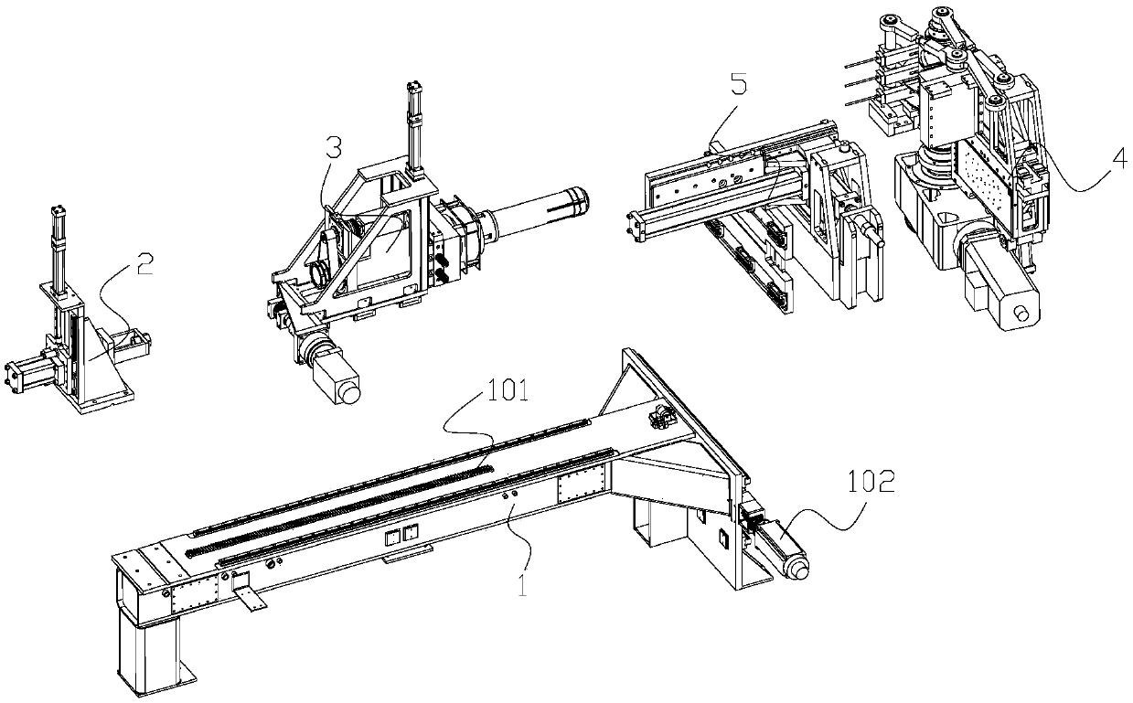
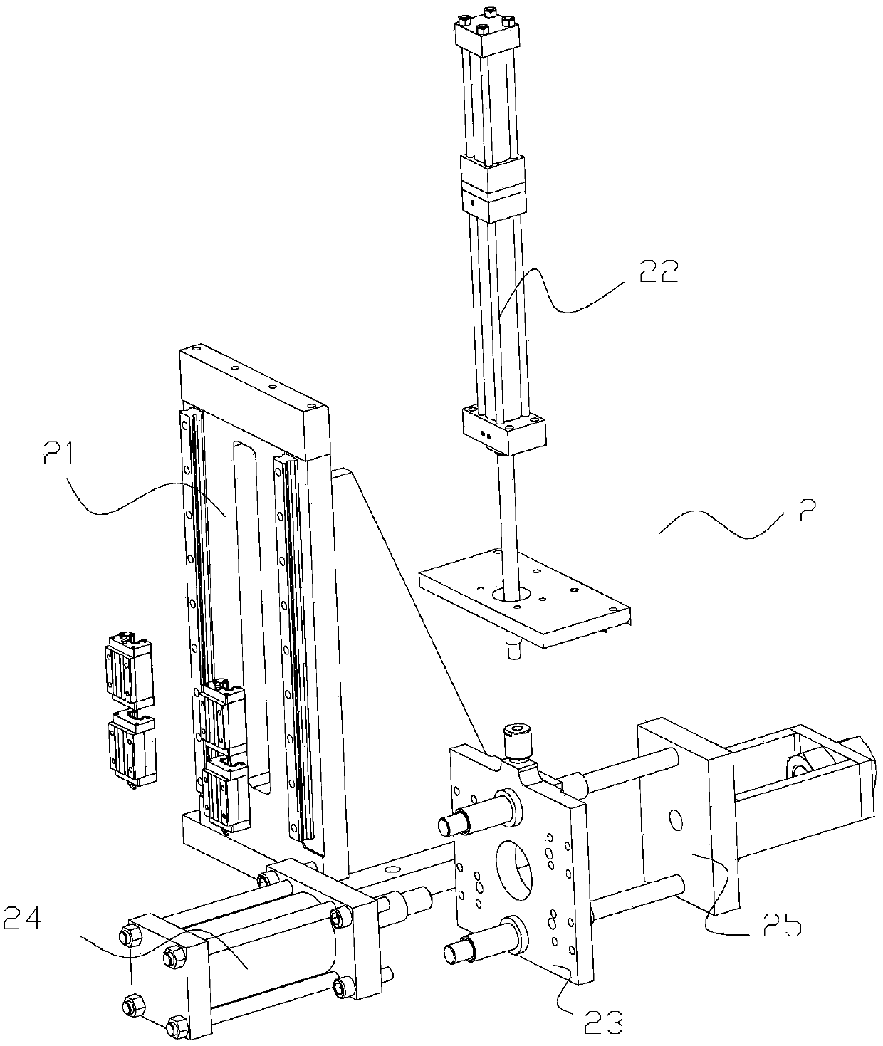
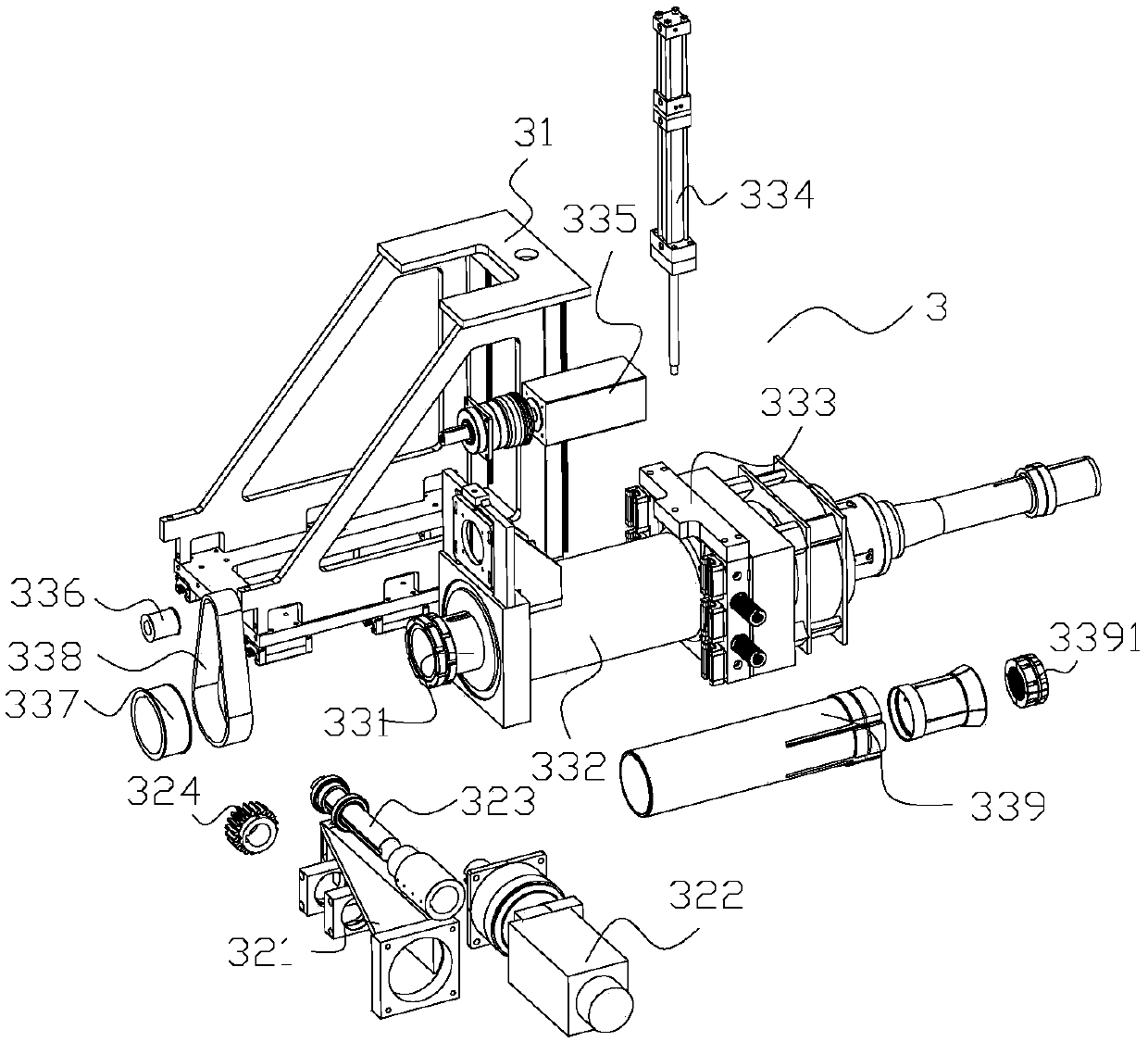
[0026] Such as figure 1 As shown, a pipe bending equipment includes a frame 1, a workpiece support device 2, a workpiece drive device 3, a pipe bending device 4 and a workpiece clamping cooperation device 5; the workpiece support device 2 is arranged on the frame 1 The end of the workpiece support device 2 is used to support the end of the workpiece; the workpiece driving device 3 includes a moving frame 31, a horizontal drive assembly and a rotating lifting assembly; the moving frame 31 is arranged on the frame 1 through a moving slide rail , the horizontal driving assembly is arranged on the moving frame 31, and the horizontal driving assembly can drive the moving frame 31 to move; the rotating lifting assembly is arranged on the moving frame 31, and the rotating lifting assembly can drive the workpiece to rota...


PUM


Abstract

The invention relates to the technical field of machines, in particular to a workpiece bending mechanism and method and a pipe bending device. The workpiece bending mechanism comprises a pipe bendingdevice and a workpiece clamping matching device. The workpiece clamping matching device is matched with the pipe bending device so that a workpiece on a workpiece driving device can be bent. The workpeice clamping matching device comprises a clamping connecting plate, a clamping hinging frame, a clamping sliding block, a clamping sliding frame, a clamping front-back air cylinder, a clamping horizontal air cylinder, a clamping horizontal connecting block and a horizontal moving plate. The pipe bending device comprises a pipe bending driving assembly, a pipe bending rotating shaft, a pipe bending shaft sleeve, a pipe bending connecting seat, a pipe bending die, a pipe bending rotating frame, a pipe bending air cylinder, a pipe bending matched plate and an auxiliary die support. The workpiecebending mechanism and method and the pipe bending device have the beneficial effects that the workpiece can be automatically bent; the pipe bending effect can be further improved, and the pipe bending quality is improved; due to the fact that the pipe bending device is matched with the workpiece clamping matching device through a hinge rod, a better pipe bending effect can be better achieved; anda better supporting limiting effect can be achieved.

Description

technical field [0001] The invention relates to the field of mechanical technology, in particular to a workpiece bending mechanism, its method and pipe bending equipment. Background technique [0002] In modern industrial manufacturing, many complex machines are assembled manually, including mobile phones and computers in the electronics industry, as well as automobile manufacturing and other household appliances. In these industrial manufacturing, many small assembly links are required to be combined together, especially in the aspect of pipe bending, through the cooperation of workers and equipment, the workpiece is taken to the designated bending point and the workpiece is fixed by clamping equipment, and then through The bending machine bends the workpiece to a specified degree of bending. After bending by manual operation, the effects of appearance uniformity, consistency, accuracy, etc. are not good, it is difficult to ensure the bending condition of the workpiece, an...

Claims


Application Information

Patent Timeline
Patent Type & Authority Applications(China)
IPC IPC(8): B21D7/00B21D43/00
CPCB21D7/00B21D43/003
Inventor 杨道救
Owner 杭州显庆科技有限公司
Why Eureka
Try Eureka