
An Intelligent Wing Composite Trailing Edge System

A composite material and trailing edge technology, applied in the direction of wing adjustment, etc., to reduce noise and improve aerodynamic efficiency

Active Publication Date: 2021-03-26
AVIC COMPOSITES
View PDF6 Cites 0 Cited by
  • Summary
  • Abstract
  • Description
  • Claims
  • Application Information

AI Technical Summary

Problems solved by technology

[0005] The purpose of the present invention is to overcome the shortcomings of the traditional deflected wing trailing edge, improve the aerodynamic efficiency of the wing and reduce the aerodynamic noise, and propose an intelligent wing composite material trailing edge system to realize the seamlessness of the wing trailing edge , smooth continuous deformation and bearing

Method used


Image

  • An Intelligent Wing Composite Trailing Edge System
  • An Intelligent Wing Composite Trailing Edge System

Examples


Embodiment Construction

[0019] The present invention is described in detail below in conjunction with accompanying drawing:

[0020] 1 Overall layout of trailing edge of intelligent composite wing

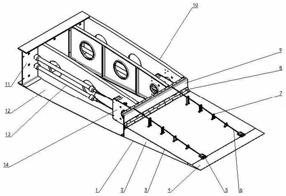
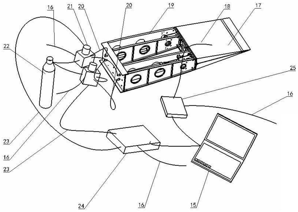
[0021] The overall layout of the trailing edge of the intelligent wing composite material is that the trailing edge is located at the rear of the wing and is seamlessly connected with the wing stabilizer 19; the trailing edge structure is a full-height honeycomb structure with a base plate; The cable 6 is connected to the end of the trailing edge, and the position of the steel cable 6 is controlled by each limit column 7, which cooperates with the control computer 15 to drive the trailing edge; the fiber grating is located in the composite material substrate 3 to realize the deformation perception of the trailing edge.

[0022] 2 trailing edge structure

[0023] The rear edge structure is composed of large deformation skin 1, flexible honeycomb 2, composite material substrate 3, limit column 7, clamp 5, ...


PUM


Abstract

The invention relates to an intelligent wing composite-material trailing edge system. A trailing edge sensing and control system is composed of a fiber grating sensor (18) and driving software. Two ends of a pneumatic muscle driver in the trailing edge driving mechanism are respectively installed and fixed at a front beam (11) and a rear beam (9) of a wing. A limiting column (7) is fixed on a composite substrate (3); a steel cable (6) passes through the hole of the limiting column (7) and then two ends are connected with the pneumatic muscle driver (13) and a trailing edge strip (4) respectively. A control computer (15) is connected with the pneumatic muscle driver (13) through an electromagnetic proportional valve (21) to drive the deformation of the trailing edge structure. According tothe invention, the aerodynamic efficiency of the wing structure can be improved; and the noise generated by the aerodynamics of the wing can be reduced. The bending of the wing can be changed based onrequirements of the flight states to realize intelligent sensing and control of the wing. Therefore, the important practical foundation is laid for engineering verification of the flexible variable-bending wing trailing edge.

Description

technical field [0001] The invention belongs to variant aircraft structure or intelligent aircraft structure technology, and relates to an intelligent wing composite trailing edge system. Background technique [0002] In recent years, with the requirements of green aviation technology for energy reduction of civil aircraft and reduction of aircraft noise, as well as the rapid development of materials and structural technologies, the movable surface of the trailing edge of the aircraft wing has gradually developed from the traditional rigid structure to the main engine. The flexible structure with wings seamlessly connected and deformable and load-bearing is called variable camber trailing edge structure. If this variable camber trailing edge structure also has sensing and control functions, it is called an intelligent trailing edge structure, an intelligent variable camber trailing edge structure or an intelligent wing variable camber trailing edge structure. The variable c...

Claims


Application Information

Patent Timeline
Patent Type & Authority Patents(China)
IPC IPC(8): B64C3/50
CPCB64C3/50
Inventor 石庆华王进尹维龙
Owner AVIC COMPOSITES
Learn More