Intelligent transport pallet capable of automatically rising and dropping to transport articles
A transport pallet, intelligent technology, applied in the field of intelligent transport pallets, can solve the problem of goods lacking lifting function, etc., to achieve the effect of enhancing practicability
- Summary
- Abstract
- Description
- Claims
- Application Information
AI Technical Summary
Problems solved by technology
Method used
Image
Examples
Embodiment 1
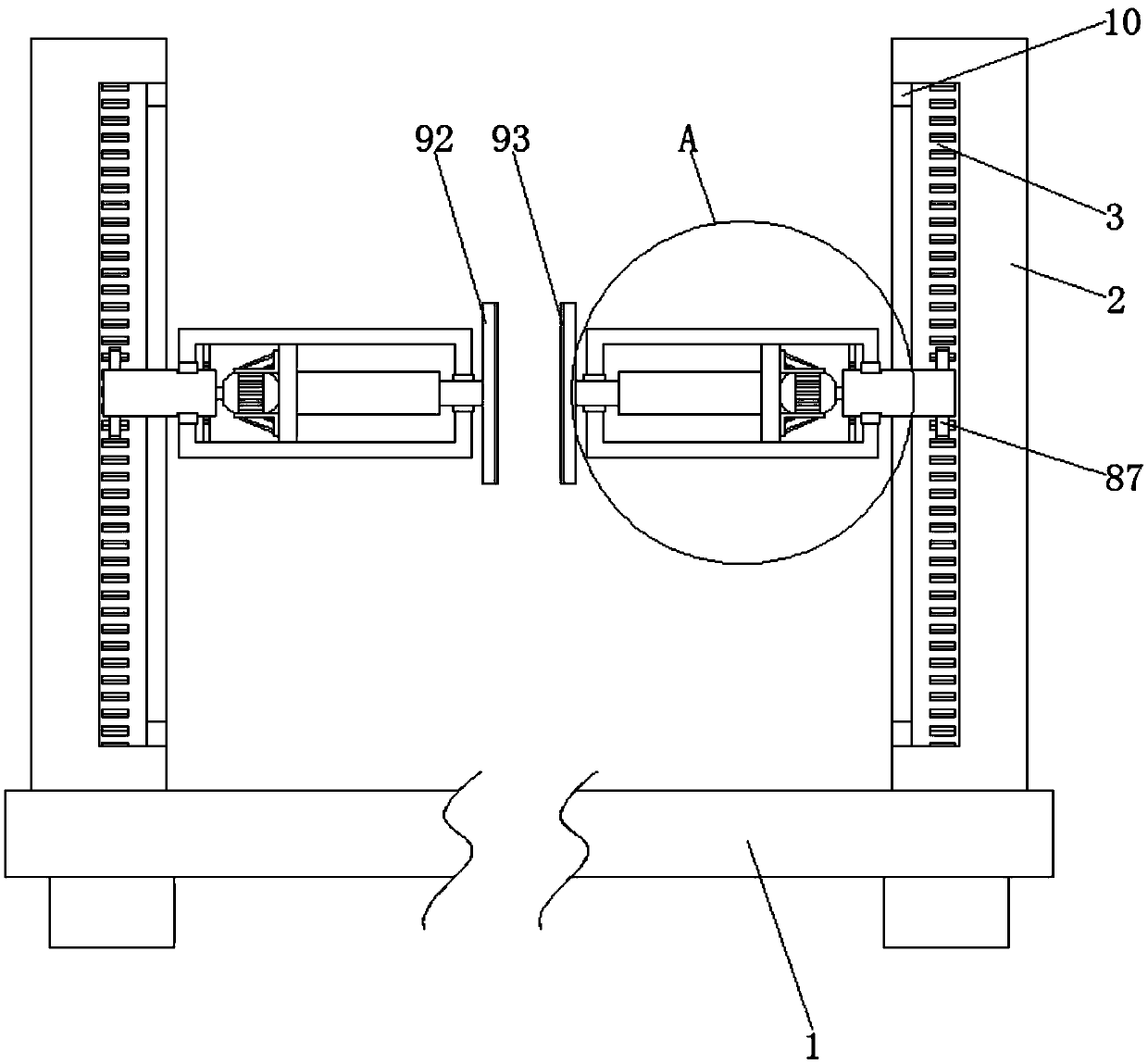
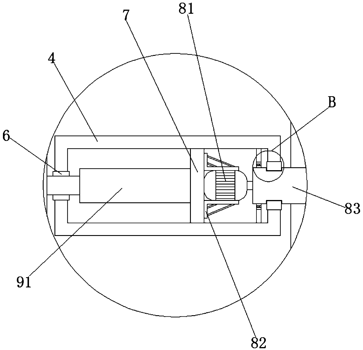
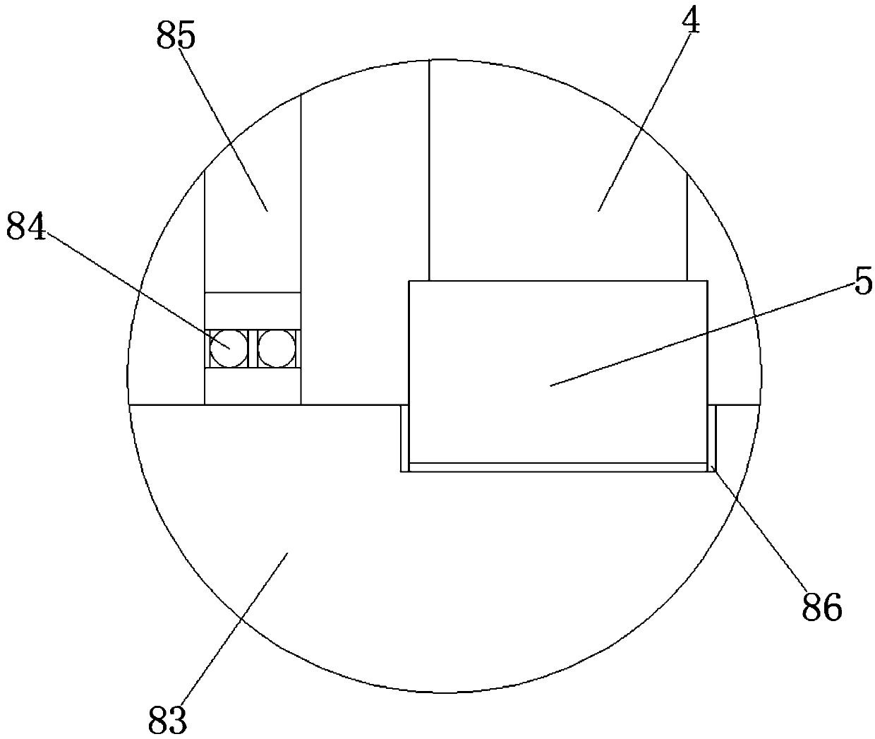
[0026] Such as Figure 1-3 As shown, an intelligent transport pallet for self-elevating and transporting goods includes a transport pallet 1, the two sides of the top of the transport pallet 1 are symmetrically fixedly connected with support columns 2, and the center of the opposite side of the support columns 2 on both sides is symmetrically provided with tooth grooves 3 , the notch of the tooth groove 3 is fixedly connected with a track plate 10, one side of the support column 2 is provided with a load-bearing column 4, and the center of the load-bearing column 4 near the side of the support column 2 is provided with a first opening, and the first opening is fixedly connected There is a support washer 5, and the center of the other side of the load-bearing column 4 is provided with a second opening, the second opening is fixedly connected with the limit washer 6, the middle part of the load-bearing column 4 inner cavity is provided with a support plate 7, and one side of the ...
Embodiment 2
[0028] On the basis of Embodiment 1, the driving mechanism 8 includes a motor 81, the top and bottom of the motor 81 are symmetrically provided with a support frame 82, an output shaft extends from the center of one side of the motor 81, and the end of the output shaft of the motor 81 is fixedly connected to the rotating shaft 83 The end of the rotating shaft 83 close to the motor 81 is sleeved with a bearing 84, the outer ring of the bearing 84 is fixedly connected to the limiting plate 85, the middle part of the rotating shaft 83 is provided with an annular limiting groove 86, and the other end of the rotating shaft 83 is sleeved with a gear 87.
Embodiment 3
[0030] On the basis of Embodiments 1 and 2, the clamping mechanism 9 includes an electric push rod 91, one end of the electric push rod 91 is fixedly connected to the clamping plate 92, and the opposite side of the clamping plate 92 on both sides is fixedly connected with a buffer pad 93 symmetrically. .
PUM
 Abstract
Description
Claims
Application Information
 - R&D
- Intellectual Property
- Life Sciences
- Materials
- Tech Scout
- Unparalleled Data Quality
- Higher Quality Content
- 60% Fewer Hallucinations
Browse by: Latest US Patents, China's latest patents, Technical Efficacy Thesaurus, Application Domain, Technology Topic, Popular Technical Reports.
© 2025 PatSnap. All rights reserved.Legal|Privacy policy|Modern Slavery Act Transparency Statement|Sitemap|About US| Contact US: help@patsnap.com


