Clear water utilization system and method in slurry pipeline transportation

A technology for pipeline transportation and ore slurry, which is applied in earth-moving drilling, wellbore/well components, construction, etc., can solve the problems of increasing pipeline transportation cost and resource waste, and achieve the effect of reducing transportation cost, waste and water consumption.

Inactive Publication Date: 2019-04-12
YUNNAN DAHONGSHAN PIPELINE
View PDF9 Cites 2 Cited by
  • Summary
  • Abstract
  • Description
  • Claims
  • Application Information

AI Technical Summary

Problems solved by technology

At this time, a large amount of clean water needs to be used, resulting in a waste of resources and increasing the cost of pipeline transportation

Method used


Image

  • Clear water utilization system and method in slurry pipeline transportation
  • Clear water utilization system and method in slurry pipeline transportation
  • Clear water utilization system and method in slurry pipeline transportation

Examples


Embodiment 1

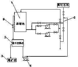
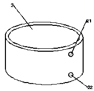
[0021] refer to Figure 1-3 As shown, the present invention provides a clean water utilization system in pulp pipeline transportation, including a thickening tank 1, and a clear water collection tank 2 is built with reinforced concrete around the thickening tank 1. Preferably, the clean water collection tank 2 is designed to be cylindrical and has a volume of 200m³, a water outlet is reserved at the bottom of the clean water collection tank 2 as the water intake 22, and a water outlet is also reserved at the top of the clean water collection tank 2 as the overflow port 21 of the clean water collection tank 2, and a water pump is installed near the water intake 22 4. The water pump 4 is connected to the water intake 22, and the water outlet of the water pump 4 is connected to the main pipeline 5 through a pipeline, and the overflow port 21 at the top of the clear water collection tank 2 is connected to the tailings dam 3 through a pipeline, and is used to drain excess The clear...

Embodiment 2

[0023] On the basis of the above embodiment, another embodiment of the present invention is that in order to ensure that the water pump 4 has strong power, the water pump 4 is a centrifugal clean water pump, the flow rate of the centrifugal clean water pump is 80m³ / h, and the lift is 70m .

Embodiment 3

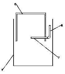
[0025] On the basis of the above-mentioned embodiment, another embodiment of the present invention is that described buoyancy tank 6 is to weld a long 1.5m wide 1m high 0.5m cuboid with a steel plate of 4mm, and this cuboid is inverted on the water surface, for Ensure that the buoyant tank 6 can freely drop 2 meters with the water surface to facilitate water intake. The length of the hose 8 inside the concentration tank 1 is at least 2m, and a valve 9 is installed on the hose 8 outside the concentration tank 1 .


PUM


Abstract

The invention discloses a clear water utilization system in slurry pipeline transportation. The clear water utilization system in slurry pipeline transportation comprises a concentration tank. A clearwater collection tank is built on the periphery of the concentration tank by adopting reinforced concrete; a water outlet is reserved at the bottom of the clear water collection tank to serve as a water intake; a water outlet is further reserved at the top of the clear water collection tank to serve as an overflow port of the clear water collection tank; a water pump is installed near the water intake; the water pump is connected with the water intake; and a water outlet of the water pump is connected with a main pipeline through a pipeline. The overflow port in the top of the clear water collection tank is connected to a tailing dam through a pipeline for conveying excess clear water to the tailing dam; a floating tank is inverted on the water surface of the concentration tank; a steel pipe is welded to the position, close to the bottom, of the side surface of the floating tank and communicates with the inside of the floating tank; the end of the steel pipe at the outer side of the floating tank is connected with a hose; and the other end of the hose communicates with the clear water collection tank. The invention further provides a clean water utilization method of the system, water resources are saved, and the transportation cost of the slurry pipeline is saved through the system and method.

Description

technical field [0001] The invention relates to the field of pulp pipeline transportation, in particular to a clear water utilization system and method in pulp pipeline transportation. Background technique [0002] In the pipeline transportation process, there is a concentration pool at the starting point to concentrate the pulp with a concentration of about 20%-35% selected by the production selection, and then transport it by pipeline after increasing the concentration. While the concentration tank is concentrating the ore slurry, the excess clear water overflows from the overflow port of the concentration tank and is discharged to the tailings dam. Due to the requirements of the slurry pipeline transportation process, whenever the pipeline stops transporting the slurry, water must be used to push the slurry in the pipeline to the terminal before the pipeline can be stopped. At this time, a large amount of clear water needs to be used, resulting in waste of resources and ...

Claims


Application Information

Patent Timeline
Patent Type & Authority Applications(China)
IPC IPC(8): E21B21/01E21B21/06
CPCE21B21/01E21B21/06
Inventor 李斌赵增佳韩军刚马波李娜
Owner YUNNAN DAHONGSHAN PIPELINE
Why Eureka
Try Eureka