Air conditioning temperature control system and control method based on temperature difference of energy storage battery

A control method and energy storage battery technology, applied in the field of energy storage, can solve the problems of reducing battery life, temperature control lag, poor fan cooling capacity, etc., so as to reduce abnormal system operation, prevent temperature control lag, and increase service life. Effect

Active Publication Date: 2020-12-01
SHENZHEN CLOU ELECTRONICS
View PDF7 Cites 0 Cited by
  • Summary
  • Abstract
  • Description
  • Claims
  • Application Information

AI Technical Summary

Problems solved by technology

[0002] The thermal management of existing energy storage systems mostly adopts fan control. If the system is charged and discharged with high power, the cooling capacity of the fan is poor and cannot effectively reduce the battery temperature in a timely manner. If the system works in a cold area, the fan control method has no heating function. The whole system will work in an unsuitable temperature range, and the battery will work in an unsuitable temperature range for a long time, which will greatly reduce the battery life and even cause abnormal system operation
[0003] The high-power energy storage system relies on the air conditioner itself for thermal management. In this way, the internal control of the air conditioner is automatic. In the existing technology, the total average temperature of the container is calculated by collecting the temperature at the top and bottom of the container. By comparing the total average temperature with the first The first preset temperature and the second preset temperature are used to control the switching of the cooling, heating, and standby functions of the air conditioner. The temperature feedback point is the indoor ambient temperature, but the energy storage system focuses on the battery temperature, so there is a relative lag in temperature control. It cannot effectively solve the temperature difference of the battery, and there are problems such as low efficiency and affecting the normal operation of the system

Method used

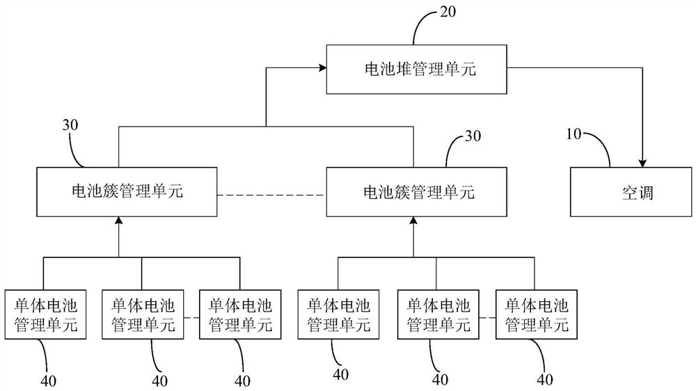
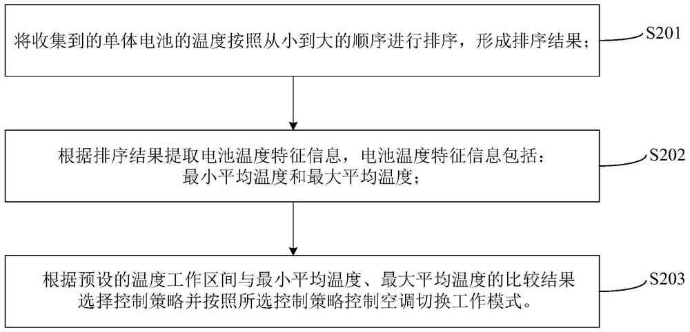

Image

  • Air conditioning temperature control system and control method based on temperature difference of energy storage battery
  • Air conditioning temperature control system and control method based on temperature difference of energy storage battery
  • Air conditioning temperature control system and control method based on temperature difference of energy storage battery

Examples


Embodiment Construction

[0052] In order to make the object, technical solution and advantages of the present invention clearer, the present invention will be further described in detail below in conjunction with the accompanying drawings and specific embodiments. It should be understood that the specific embodiments described here are only used to explain the present invention, not to limit the present invention.

[0053] In order to make the description of the present disclosure more detailed and complete, the following provides an illustrative description of the implementation modes and specific examples of the present invention; but this is not the only form for implementing or using the specific embodiments of the present invention. The description covers features of various embodiments as well as method steps and their sequences for constructing and operating those embodiments. However, other embodiments can also be used to achieve the same or equivalent functions and step sequences.

[0054] The...


PUM


Abstract

The invention relates to the technical field of energy storage, in particular to an energy storage battery temperature difference-based air conditioner temperature control system and a control method.An air conditioner is used for effectively refrigerating and cooling, the temperature of a single battery can be effectively adjusted in real time, the problem of non-uniform temperature distributionafter a plurality of single batteries runs for a long time is solved, the abnormal condition of system running is reduced, the service lifetime of an energy storage system is prolonged, the temperature of the single battery is used as a feedback point of temperature adjustment of the air conditioner, and the problem of temperature control lag is prevented.

Description

technical field [0001] The invention relates to the field of energy storage technology, in particular to an air conditioner temperature control system and control method based on temperature differences of energy storage batteries. Background technique [0002] The thermal management of existing energy storage systems mostly adopts fan control. If the system is charged and discharged with high power, the cooling capacity of the fan is poor and cannot effectively reduce the battery temperature in a timely manner. If the system works in a cold area, the fan control method has no heating function. The entire system will work in an unsuitable temperature range, and the battery will work in an unsuitable temperature range for a long time, which will greatly reduce the battery life and even cause abnormal system operation. [0003] The high-power energy storage system relies on the air conditioner itself for thermal management. In this way, the internal control of the air conditio...

Claims


Application Information

Patent Timeline
Patent Type & Authority Patents(China)
IPC IPC(8): H01M10/617H01M10/633H01M10/663
CPCH01M10/617H01M10/633H01M10/663Y02E60/10
Inventor 叶天意
Owner SHENZHEN CLOU ELECTRONICS
Why Eureka
Try Eureka