
Antenna structure and electronics

A technology of antenna structure and electronic equipment, which is applied in the field of electronic equipment and antenna structure, can solve the problems of inability to achieve full horizontal coverage and high antenna directivity coefficient, and achieve the effect of reducing directivity coefficient and improving horizontal plane radiation

Active Publication Date: 2021-10-26
GOERTEK INC
View PDF11 Cites 0 Cited by
  • Summary
  • Abstract
  • Description
  • Claims
  • Application Information

AI Technical Summary

Problems solved by technology

[0004] The main purpose of the present invention is to propose an antenna structure, which aims to solve the problem that the directivity coefficient of the antenna in the electronic equipment in the prior art is too high to achieve horizontal full coverage, reduce the directivity coefficient of the antenna, and improve its horizontal pattern , increase the horizontal plane radiation

Method used


Image

  • Antenna structure and electronics
  • Antenna structure and electronics
  • Antenna structure and electronics

Examples


Embodiment Construction

[0032] Next, the technical solutions in the embodiments of the present invention will be described in the following examples, and the described embodiments are merely, not all of the embodiments of the present invention. Based on the embodiments in the present invention, all other embodiments obtained without creative labor are not made in the premise of creative labor.

[0033] It should be noted that all directional instructions (such as above, lower, left, right, front, and post, ...) are only used in a particular attitude (as shown in the accompanying drawings). The relative positional relationship, movement conditions, etc., if the specific posture changes, the directional indication is also changed accordingly.

[0034] Further, in the present invention, "first", "second", and the like are intended to be intended to describe purposes only, and cannot be understood as an indication or implies its relative importance or implicitly indicated the number of technical features ind...


PUM


Abstract

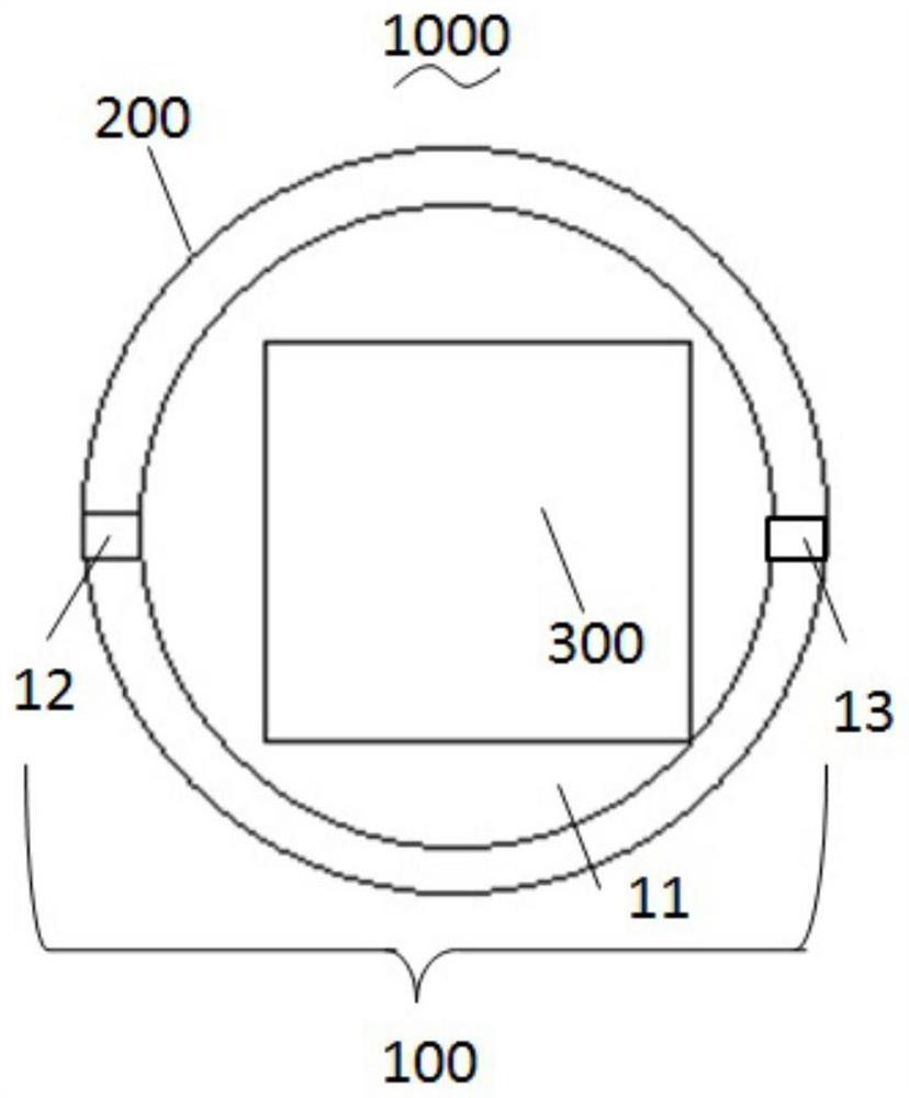
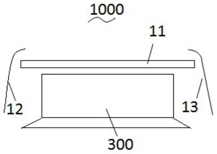
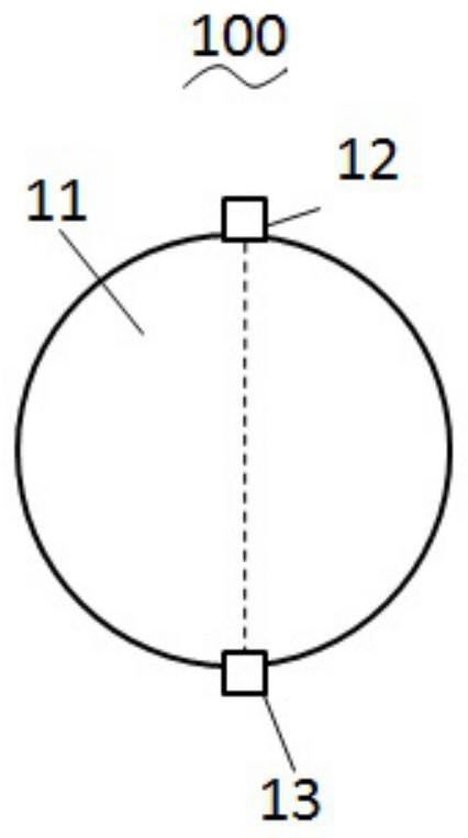
The invention discloses an antenna structure and electronic equipment using the antenna structure, wherein the antenna structure includes: a main board and a main antenna, the main antenna is arranged on the edge of the main board, and the edge of the main board is also provided with The parasitic antenna of the main antenna, the parasitic antenna is spaced apart from the main antenna. The invention reduces the directivity coefficient of the main antenna, improves its horizontal pattern and increases the horizontal plane radiation.

Description

Technical field [0001] The present invention relates to the field of antenna technology, and more particularly to an antenna structure and an electronic device applied to the antenna structure. Background technique [0002] In real life, with the development of intelligent home and artificial intelligence technology, various electronic devices that provide smart home features and artificial intelligence are loved by consumers. [0003] An arbitrary position of the electronic device is in the room, the ideal antenna should be covered in the horizontal, but in the electronic device, the antenna size is much smaller than the main board, the speaker or the radiator size, and the metal reflection of these components is blocked, electronic equipment The directional coefficient of the antenna is greater than 4, and it is difficult to achieve horizontal all-end coverage. Inventive content [0004] The primary object of the present invention is to propose an antenna structure to solve th...

Claims


Application Information

Patent Timeline
Patent Type & Authority Patents(China)
IPC IPC(8): H01Q1/22H01Q1/50H01Q21/29H04R1/20
CPCH01Q1/22H01Q1/50H01Q21/29H01Q21/293H04R1/20
Inventor 何其娟王嘉鸣
Owner GOERTEK INC
Learn More