Stealth antenna and stealth antenna array based on ultra-wideband low radar cross-section based on phase change film
A radar cross-section and ultra-broadband technology, which is applied to antennas, radiating unit covers, and radiating element structures, can solve the problems of antenna radiation performance degradation, achieve circuit area reduction, scan beam narrowing, and feeder network simplification Effect
- Summary
- Abstract
- Description
- Claims
- Application Information
AI Technical Summary
Problems solved by technology
Method used
Image
Examples
Embodiment 1
[0043] A stealth antenna with ultra-wideband and low radar cross-section based on phase-change film
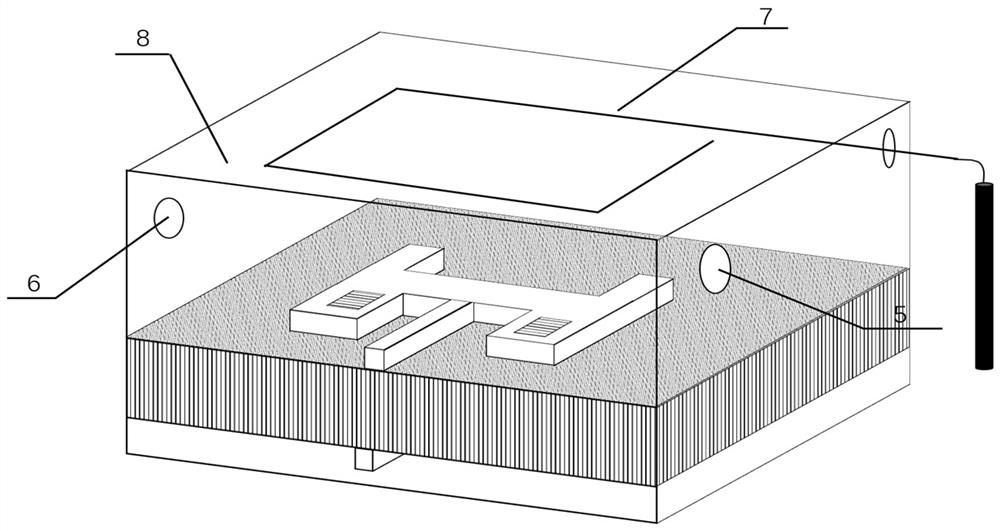
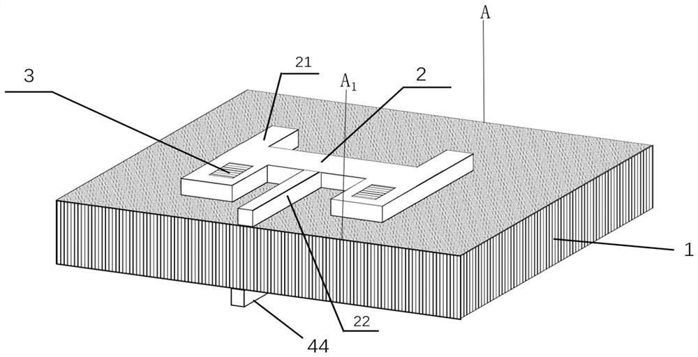
[0044] see figure 1 , figure 2 , the stealth antenna includes a dielectric substrate 1 , an H-shaped metal patch 2 , a ground plate 4 and a heat shield 8 .
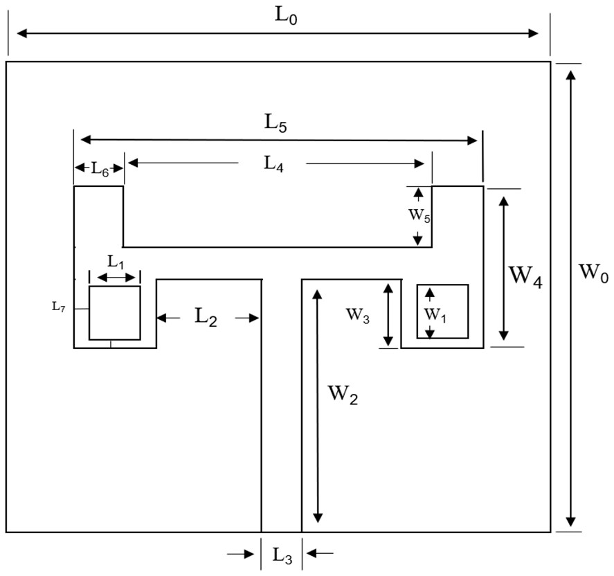
[0045] see figure 2 , the material of the dielectric substrate 1 is sapphire. The H-shaped metal patch 2 is arranged on one side of the dielectric substrate 1 , the horizontal patch lower part of the H-shaped metal patch 2 is connected to the patch transmission line 22 , and the patch transmission line 22 extends to the edge of the dielectric substrate 1 . The two vertical patches 21 of the H-shaped metal patch 2 on both sides of the patch transmission line 22 are respectively embedded with a phase change film 3; the material of the phase change film 3 is vanadium dioxide (VO 2 ), when the phase change film 3 is at the operating temperature, the conductivity is 10 6 S / m.
[0046] The preparation operation of the p...
Embodiment 2
[0056] Stealth antenna array based on the stealth antenna of embodiment 1 as an antenna unit
[0057] see Figure 7 , the stealth antenna array includes four stealth antennas and power divider 9, the patch transmission lines 22 of the four stealth antennas are connected in parallel to the high impedance line 91 of the power divider 9, the outer end of the high impedance line 91 of the power divider 9 and Outer ends of the low impedance lines 92 respectively extend to the edges of the dielectric substrate 1 .
[0058] see Figure 8 , a structure on one side of the ground plate 4 of the four stealth antennas.
[0059] The working frequency band of the stealth antenna array of the present embodiment 2 is 6-12GHz, the resonant frequency is 9.0GHz, and the working wavelength is λ 0 =1.185mm. The size parameters of each stealth antenna are the same as those in Embodiment 1.
[0060] see Figure 7 , on the basis of the stealth antenna in Embodiment 1, the distance between the a...
PUM
| Property | Measurement | Unit |
|---|---|---|
| electrical conductivity | aaaaa | aaaaa |
| thermal resistance | aaaaa | aaaaa |
| length | aaaaa | aaaaa |
Abstract
Description
Claims
Application Information
 - R&D
- Intellectual Property
- Life Sciences
- Materials
- Tech Scout
- Unparalleled Data Quality
- Higher Quality Content
- 60% Fewer Hallucinations
Browse by: Latest US Patents, China's latest patents, Technical Efficacy Thesaurus, Application Domain, Technology Topic, Popular Technical Reports.
© 2025 PatSnap. All rights reserved.Legal|Privacy policy|Modern Slavery Act Transparency Statement|Sitemap|About US| Contact US: help@patsnap.com


