
Adjustable capacitive coupling structure

A capacitive coupling and adjustable technology, which is applied to circuits, electrical components, waveguide devices, etc., can solve problems such as increased labor costs, extended debugging time, and size deviation of capacitive coupling structures, so as to improve the adjustment range and reduce the difficulty of debugging , Reduce the effect of debugging time

Pending Publication Date: 2019-12-03
苏州诺泰信通讯有限公司
View PDF0 Cites 0 Cited by
  • Summary
  • Abstract
  • Description
  • Claims
  • Application Information

AI Technical Summary

Problems solved by technology

[0003] At present, the capacitive coupling structure of dumbbell shape and probe structure has been widely used in filters because of its easy manufacture and convenient processing. However, when the multiple zeros of the filter are at the low end of the passband , the size of the capacitive coupling structure is very sensitive to the strength of the zero point; in the actual production process, due to processing tolerances and human assembly errors, it is inevitable that the distance between the capacitive coupling structure and the resonant rod will be deviated, which eventually leads to the capacitive coupling structure. Strong and weak are difficult to control
[0004] Due to the deviation of the structure size of the capacitive coupling, it brings many problems to the mass production of the filter, which is specifically manifested in: when the performance index of the filter can meet the requirements, the difficulty of debugging the whole filter is increased due to the critical index, thus prolonging the It shortens its debugging time, and finally increases its labor cost; when the performance index of the filter does not meet the requirements, it is necessary to strengthen or weaken the capacitive coupling structure to a certain extent, so it is necessary to disassemble the whole filter and replace it with different sizes of capacitive coupling structure, and finally reassemble and debug the whole machine. Due to the rework of the whole machine, the production cost of the filter will eventually increase significantly
[0005] Therefore, the adjustment of the capacitive coupling structure is very important. At present, the adjustment of the capacitive coupling structure is usually achieved by moving its support structure and then moving the capacitive coupling structure. However, this method needs to open the filter cover on the one hand, which is time-consuming and laborious. , on the other hand, its adjustable range is limited and difficult to control

Method used


Image

  • Adjustable capacitive coupling structure
  • Adjustable capacitive coupling structure
  • Adjustable capacitive coupling structure

Examples


Embodiment 1

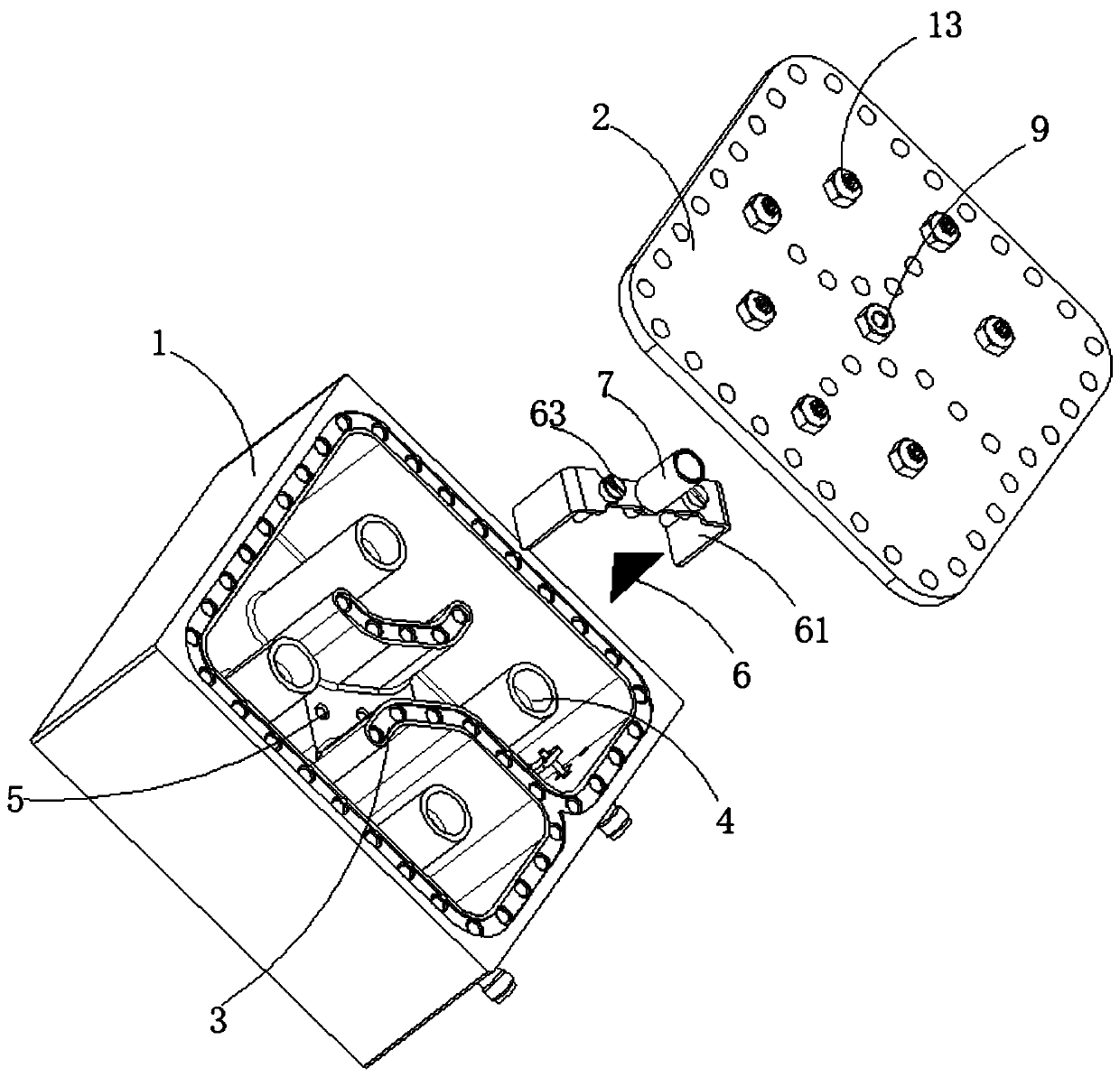
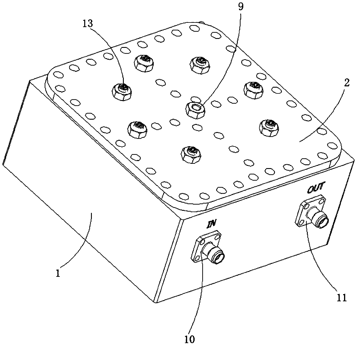
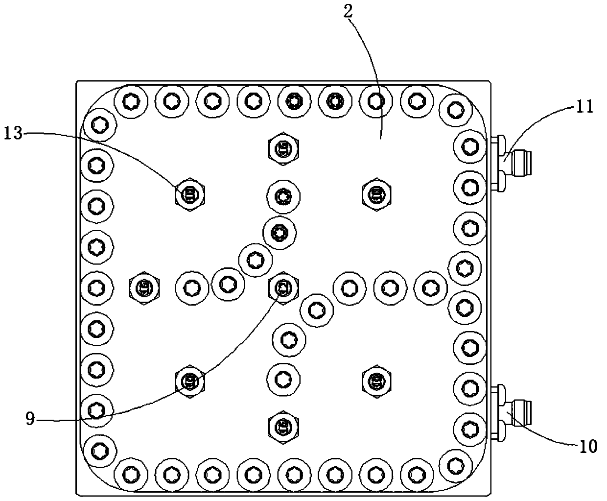
[0035] Such as Figure 1 to Figure 5 The adjustable capacitive coupling structure shown, including

[0036] chamber 1;

[0037] The cover plate 2 is detachably connected to the top of the cavity 1;

[0038] Also includes

[0039] The partition wall 3 is arranged in the cavity 1, and the cavity 1 is divided into a plurality of resonant cavities by the partition wall 3;

[0040] The resonant rod 4 is arranged in the resonant cavity and fixedly connected to the bottom inner wall of the cavity 1;

[0041] The slot 5 is opened on the partition wall 3

[0042] Capacitive coupling assembly 6: including capacitive coupling copper sheet 61, capacitive support 62 and dielectric screw 63, the dielectric screw 63 is connected in the slot 5, capacitive coupling copper 61 and capacitive support 62 are equipped with Cooperating slotting, the capacitive coupling copper sheet 61 and the capacitive support member 62 are connected to the top of the partition wall 3 through the dielectric sc...

Embodiment 2

[0052] Such as Figure 1-6 The adjustable capacitive coupling structure shown, including

[0053] chamber 1;

[0054] The cover plate 2 is detachably connected to the top of the cavity 1;

[0055] Also includes

[0056] The partition wall 3 is arranged in the cavity 1, and the cavity 1 is divided into a plurality of resonant cavities by the partition wall 3;

[0057] The resonant rod 4 is arranged in the resonant cavity and fixedly connected to the bottom inner wall of the cavity 1;

[0058] The slotted hole 5 is opened on the partition wall 3

[0059] Capacitive coupling assembly 6: including capacitive coupling copper sheet 61, capacitive support 62 and dielectric screw 63, the dielectric screw 63 is connected in the slot 5, capacitive coupling copper 61 and capacitive support 62 are equipped with Cooperating slotting, the capacitive coupling copper sheet 61 and the capacitive support member 62 are connected to the top of the partition wall 3 through the dielectric scre...


PUM


Abstract

The invention discloses an adjustable capacitive coupling structure. The adjustable capacitive coupling structure comprises: a cavity; isolation walls arranged in the cavity, wherein the cavity is divided into a plurality of resonant cavities through the isolation walls; resonant rods arranged in the resonant cavities; slotted hole formed in the isolation walls; and a capacitive coupling component. According to the adjustable capacitive coupling structure, the lengths of adjusting screws at the bottom of the cavity screwed into the resonant cavities are adjusted, the distance between the capacitance coupling component and the capacitance coupling tuning screw rods is adjusted, the height of the isolation walls are adjusted, and the depths of tuning bolts screwed into the I-shaped grooves of the capacitive coupling resonators is combined, so that the functions of fine tuning and coarse tuning of the capacitive coupling strength are achieved, the adjustment range of the capacitive coupling strength is improved, and the cover plate is prevented from being disassembled for debugging, the debugging difficulty of the whole filter is reduced, the debugging time is shortened, the assemblyof the capacitive coupling copper sheet is achieved through the matching of the dielectric screws and the slotted holes, the connection reliability is high, and the use is convenient.

Description

technical field [0001] The invention relates to an adjustable capacitive coupling structure, which belongs to the technical field of wireless communication. Background technique [0002] With the continuous development of communication technology, communication frequency resources are becoming more and more tight, and more and more stringent requirements are put forward for filter loss and out-of-band suppression. More and more filters are in the passband 5MHz, 3MHz, 2MHz or even 1.5MHz have higher near-end suppression requirements, and then need multiple transmission zeros to meet. When these transmission zeros are at the low end of the passband, we generally implement them through capacitive coupling structures. [0003] At present, the capacitive coupling structure of dumbbell shape and probe structure has been widely used in filters because of its easy manufacture and convenient processing. However, when the multiple zeros of the filter are at the low end of the passban...

Claims


Application Information

Patent Timeline
Patent Type & Authority Applications(China)
IPC IPC(8): H01P1/207
CPCH01P1/207
Inventor 史作毅梁文超汪亭
Owner 苏州诺泰信通讯有限公司
Learn More