Orthodontic time-sharing self-locking bracket

A technology of self-locking brackets and brackets, applied in brackets, arch wires, etc., can solve the problems of high production process requirements, increased patient pain, too loose and too tight self-locking structures, etc., and achieves low production process requirements. Avoid injury and pain, stable effect of self-locking structure

Pending Publication Date: 2019-04-16
吕涛
View PDF0 Cites 12 Cited by
  • Summary
  • Abstract
  • Description
  • Claims
  • Application Information

AI Technical Summary

Problems solved by technology

Common self-ligating brackets currently on the market have the following defects: 1. When self-ligating brackets use thin arch wires in the first stage: severely misaligned teeth are likely to cause excessive force on the teeth when the arch wire is fully in place and the sliding cover is closed , leading to increased risk of tooth loosening, root bone adhesion, and root resorption, which increases patient pain; 2. When using thicker square wires in the second stage of self-ligating brackets, the archwires must be placed in the grooves, and the size of the archwires must be smaller than The size of the groove (because it is difficult for a full-size archwire to fully enter the groove, or the correction force is too large), this leads to an inevitable gap between the inner wall of the groove and the archwire, and the current self-locking cover plate structure is also Unable to fix the arch wire in the groove to eliminate the gap, which directly affects the accurate expression of the bracket preset data, and affects the treatment process and effect; 3. The self-locking structure is complex and occupies a large space, making the bracket wings short and round Blunt, not easy to tie ligation wire and chain aprons; 4. The production process requires high requirements, and the self-locking structure is easy to be too loose or too tight or easy to be damaged

Method used


Image

  • Orthodontic time-sharing self-locking bracket
  • Orthodontic time-sharing self-locking bracket
  • Orthodontic time-sharing self-locking bracket

Examples


Embodiment Construction

[0027] In order to clearly illustrate the technical features of this solution, the present invention will be described in detail below through specific implementation modes and in conjunction with the accompanying drawings.

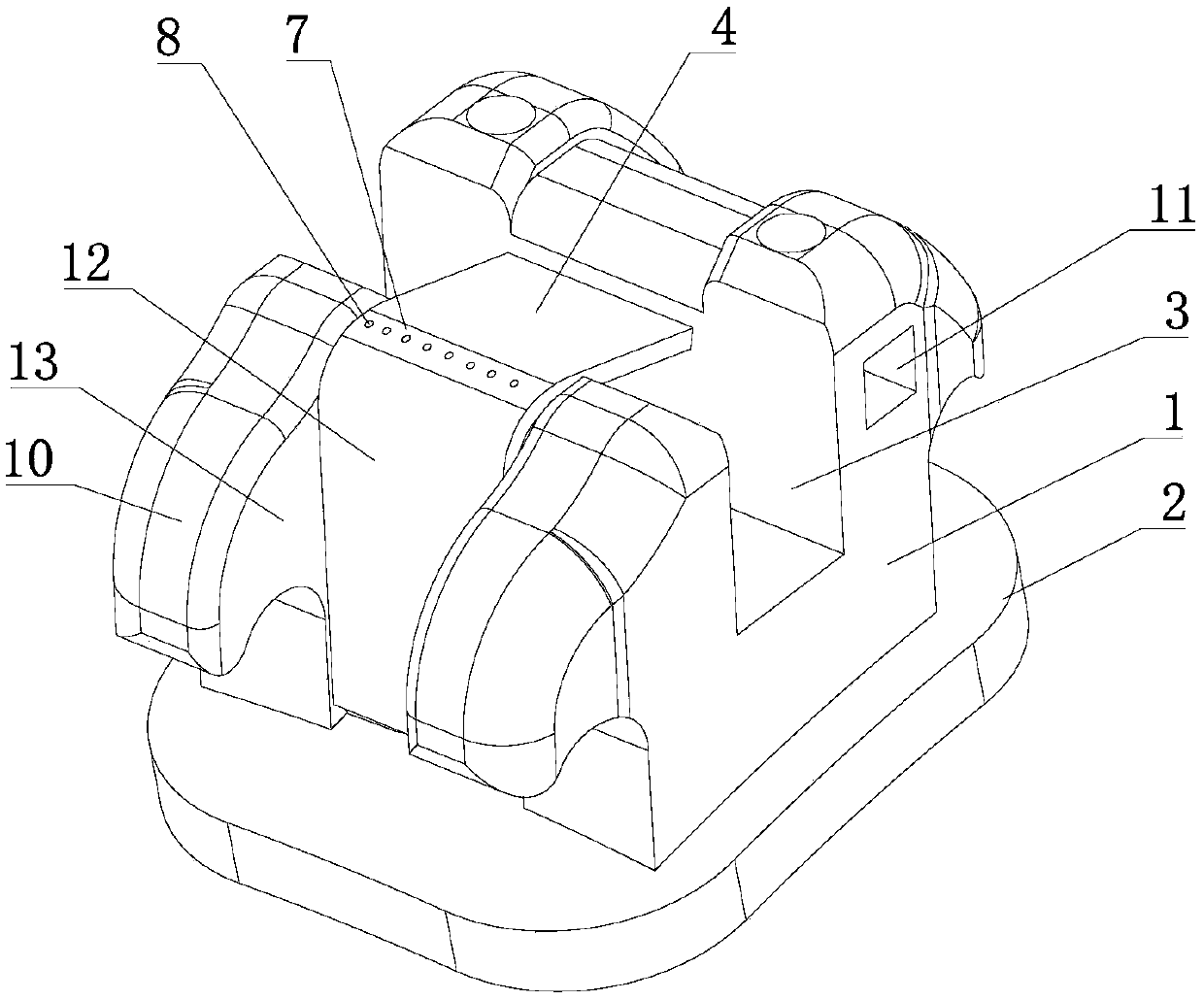
[0028] Such as Figure 1-7 As shown, a time-sharing self-ligating bracket for orthodontics is characterized in that it includes:

[0029] A bracket main body 1, a bracket bottom plate 2 in contact with teeth is provided at the bottom of the bracket main body 1, and a bracket groove 3 for installing an archwire is provided on the bracket main body 1;

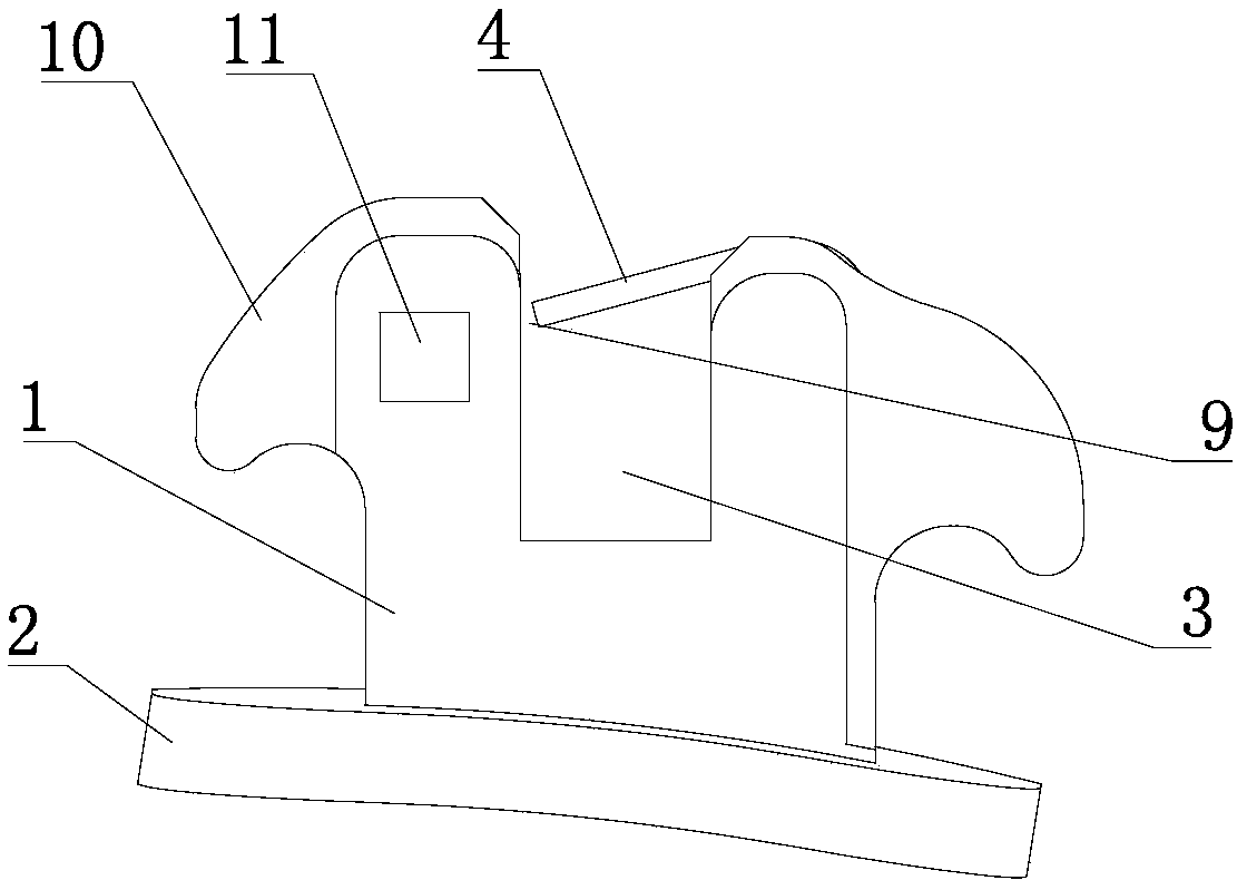
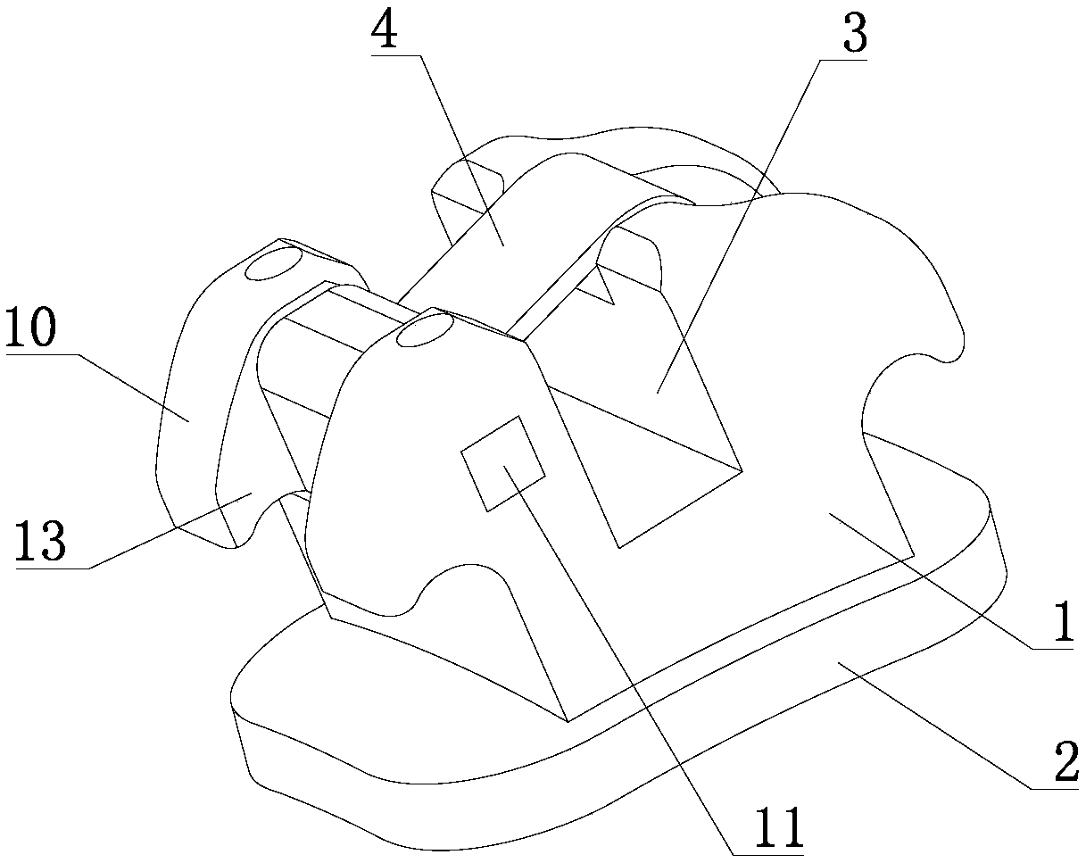
[0030] The time-sharing self-locking unit includes an elastic pressing plate 4 arranged on the side wall of the bracket groove 3, and the elastic pressing plate 4 defines a channel 9 with variable dimensions;

[0031] as attached Figure 4 , 5 As shown, the elastic pressing plate 4 has a first working state and a second working state; in the first working state, the thin arch wire 5 having a radial dimens...


PUM


Abstract

The invention relates to the field of orthodontic brackets, in particular to an orthodontic time-sharing self-locking bracket comprising a bracket main body and a time-sharing self-locking unit, wherein the bottom of the bracket main body is provided with a bracket base plate in contact with the teeth, and the bracket main body is provided with a bracket groove for mounting an arch wire; the time-sharing self-locking unit includes an elastic pressure plate disposed on a side wall of the bracket groove, and the elastic pressure plate defines a variable-size passage; and the elastic pressure plate has a first working state and a second working state. The orthodontic time-sharing self-locking bracket is exquisite in structure design; the different working states of the elastic pressure plateare reasonably used in different time periods of orthodontic treatment, and a doctor can press the arch wire into the bracket groove conveniently at an early stage, the operation is simple, the friction between the arch wire and the groove is low, and the tooth movement is safe and efficient; at a later stage, a thick square wire presses the elastic pressure plate to the side wall of the groove tofill the clearance, the friction between the arch wire and the groove is high, the precise control of a tooth torque, shaft inclination and position is achieved, the orthodontic effect is greatly improved, and an orthodontic treatment course is shortened.

Description

technical field [0001] The invention relates to the field of orthodontic brackets, in particular to an orthodontic time-sharing self-locking bracket. Background technique [0002] At present, the existing orthodontic brackets can be divided into two types from the clinical ligation methods: traditional ligation brackets and self-ligating brackets. The self-ligating bracket replaces the traditional ligation operation through the self-locking structure of the bracket, which reduces the friction between the bracket groove and the arch wire, and has the advantages of convenient and efficient clinical operation, soft orthodontic force, and fast tooth movement. [0003] Orthodontic treatment can be roughly divided into two stages according to the thickness of the arch wire used. The first stage is to use the thin arch wire to act on the tooth bracket groove in the early stage to align and level the teeth. The second stage is to use the thick arch wire Control the root of the toot...

Claims


Application Information

Patent Timeline
Patent Type & Authority Applications(China)
IPC IPC(8): A61C7/30
CPCA61C7/30
Inventor 吕涛
Owner 吕涛
Why Eureka
Try Eureka