An injection-type soil remediation and treatment integrated equipment

A soil remediation and injection technology, applied in the field of soil pollution control, can solve problems such as ground potholes, limited depth of action, and complicated steps.

Active Publication Date: 2020-10-30
运城地福来生物科技发展有限公司
View PDF5 Cites 0 Cited by
  • Summary
  • Abstract
  • Description
  • Claims
  • Application Information

AI Technical Summary

Problems solved by technology

[0005] For soil remediation in the prior art, one is to spray the chemical on the spot, this method relies on the way of infiltration, the depth of action is limited, and it is easy to volatilize; the other is to dig out the polluted soil and carry out Chemical mixing treatment, this method is easy to cause potholes on the ground, the steps are more complicated, and the cost is higher

Method used


Image

  • An injection-type soil remediation and treatment integrated equipment
  • An injection-type soil remediation and treatment integrated equipment
  • An injection-type soil remediation and treatment integrated equipment

Examples


Embodiment 1

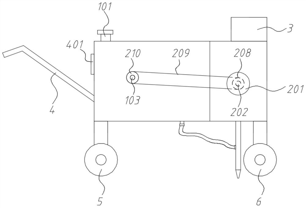
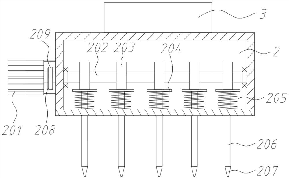
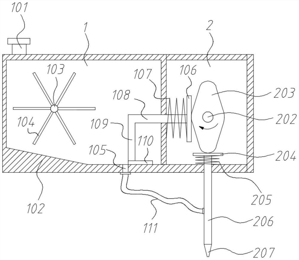
[0039] An injection-type integrated equipment for soil remediation and treatment, including a housing, a power supply 3, a No. 1 roller assembly 5, and a No. 2 roller assembly 6;

[0040] A partition is fixed in the shell, which divides the inner cavity of the shell into a drug storage chamber 1 and a working chamber 2; the working chamber 2 is equipped with a No. 1 rotating shaft 202 in the front and rear directions, and a number of shuttle-shaped cams are evenly spaced on the No. 1 rotating shaft 202 203; a No. 1 pressing plate 204 is arranged below the shuttle cam 203, and a No. 1 spring 205 is connected between the No. 1 pressing plate 204 and the bottom plate of the working chamber 2. The No. 1 pressing plate 204 is connected downward with an injection tube 206, and the bottom end of the injection tube 206 passes through the working chamber. Cavity 2; the left side of shuttle cam 203 is provided with No. 2 pressing plate 106, is connected with No. 2 spring 107 between No. ...

Embodiment 2

[0045] An injection-type integrated equipment for soil remediation and treatment, including a housing, a power supply 3, a No. 1 roller assembly 5, and a No. 2 roller assembly 6;

[0046] A partition is fixed in the shell, which divides the inner cavity of the shell into a drug storage chamber 1 and a working chamber 2; the working chamber 2 is equipped with a No. 1 rotating shaft 202 in the front and rear directions, and a number of shuttle-shaped cams are evenly spaced on the No. 1 rotating shaft 202 203; a No. 1 pressing plate 204 is arranged below the shuttle cam 203, and a No. 1 spring 205 is connected between the No. 1 pressing plate 204 and the bottom plate of the working chamber 2. The No. 1 pressing plate 204 is connected downward with an injection tube 206, and the bottom end of the injection tube 206 passes through the working chamber. Cavity 2; the left side of shuttle cam 203 is provided with No. 2 pressing plate 106, is connected with No. 2 spring 107 between No. ...

Embodiment 3

[0052] An injection-type integrated equipment for soil remediation and treatment, including a housing, a power supply 3, a No. 1 roller assembly 5, and a No. 2 roller assembly 6;

[0053] A partition is fixed in the shell, which divides the inner cavity of the shell into a drug storage chamber 1 and a working chamber 2; the working chamber 2 is equipped with a No. 1 rotating shaft 202 in the front and rear directions, and a number of shuttle-shaped cams are evenly spaced on the No. 1 rotating shaft 202 203; a No. 1 pressing plate 204 is arranged below the shuttle cam 203, and a No. 1 spring 205 is connected between the No. 1 pressing plate 204 and the bottom plate of the working chamber 2. The No. 1 pressing plate 204 is connected downward with an injection tube 206, and the bottom end of the injection tube 206 passes through the working chamber. Cavity 2; the left side of shuttle cam 203 is provided with No. 2 pressing plate 106, is connected with No. 2 spring 107 between No. ...


PUM


Abstract

The invention relates to the technical field of soil pollution control and treatment, in particular to injection-type soil remediation treatment integrated equipment. A first rotating shaft is drivenby a first servo motor to rotate to act on first pressing plates and second pressing plates through shuttle-shaped cams, so that injection tubes and plugging plates have a synergistic effect, the injection pipes are pressed down to be inserted into the ground, discharging ports are opened correspondingly to the plugging plates, the injection tubes are lifted to get away from the ground, and the discharging ports are sealed again by the corresponding plugging plates; in this way, the injection tubes are inserted into the ground for injection, the volatilization of a liquid agent is reduced, thefunction depth is increased, and the function effect is improved; driving pieces based on a groove wheel working principle are further arranged on rolling wheel assemblies, a second servo motor is fixed at the bottom of an agent storage chamber, a stirring disc is connected to an output end, a groove wheel is correspondingly installed on a connecting shaft, and the stirring disc rotates to intermittently drive the groove wheel to rotate, so that the equipment automatically walks and stops to adapt to the injection work.

Description

technical field [0001] The invention relates to the technical field of soil pollution control, in particular to an injection-type integrated equipment for soil restoration and treatment. Background technique [0002] Soil refers to the loose surface layer on the land surface that is fertile and capable of growing plants, and its thickness is generally about 2m. Soil not only provides mechanical support for plant growth, but also provides fertility elements such as water, fertilizer, air, and heat for plant growth and development. Due to the rapid growth of population and the rapid development of industry, solid wastes are continuously stacked and dumped on the soil surface, harmful waste water is continuously infiltrated into the soil, and harmful gases and floating dust in the atmosphere are also continuously falling into the soil with rainwater, resulting in soil pollution. All substances that hinder the normal function of the soil, reduce the yield and quality of crops, ...

Claims


Application Information

Patent Timeline
Patent Type & Authority Patents(China)
IPC IPC(8): B09C1/00B09C1/08
CPCB09C1/00B09C1/08B09C2101/00
Inventor 徐荣霞
Owner 运城地福来生物科技发展有限公司
Why Eureka
Try Eureka