Parking device for electric vehicle
A technology of electric vehicles and driving devices, applied in the direction of brakes, brake components, vehicle components, etc., can solve the problem of unstable contact between brake pads and brake discs, reduce contact instability, connect stably, and prevent vehicles from slipping Effect
Inactive Publication Date: 2019-04-16
周丰
View PDF11 Cites 2 Cited by
- Summary
- Abstract
- Description
- Claims
- Application Information
AI Technical Summary
Problems solved by technology
Aiming at the deficiencies of the prior art, the present invention provides a parking device for electric vehicles, which solves the problem of unstable contact between brake pads and brake discs when parking
Method used
View moreImage
Smart ImageViewing Examples
Examples
Embodiment Construction
Login to View More PUM
 Abstract
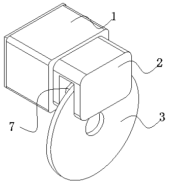
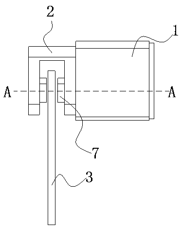
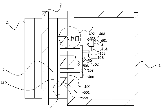
The invention provides a parking device for an electric vehicle and relates to the field of vehicle electronics. The parking device for the electric vehicle comprises a parking body, parking calipersare welded to the left side of the parking body, and a braking disc is arranged in a parking calipers U-shaped groove; the interior of the parking body is hollow, and a driving device is fixedly connected to the top of the inner wall of the parking body. According to the parking device for the electric vehicle, when an electric push rod pushes a push block to move, the push block can move along asliding inclined groove, and the sliding inclined groove is parallel to a sliding face in a wedge groove, tightly attached to a wedge block, so that when the push block pushes the wedge block to moveobliquely, the wedge block can conduct push operation along a contact face of the wedge groove and a parking braking disc can be in contact operation with a braking disc; the wedge block conducts pushing along the contact face of the wedge groove, so that connection between the braking disc and the parking braking disc is more stable, and the situation is reduced that the parking braking disc is in unstable contact with the braking disc.
Description
technical field The invention relates to the field of automotive electronics, in particular to a parking device for an electric vehicle. Background technique The parking brake usually refers to the manual brake installed on the motor vehicle, referred to as the hand brake, which is used to stabilize the vehicle after the vehicle has come to a complete stop, so as to avoid accidents caused by rolling when the vehicle is parked on a slope. The common handbrake is generally placed in the drooping position of the driver's right hand, which is easy to use. At present, some automatic transmission models on the market are equipped with a foot brake with the same function as the hand brake on the outside of the driver's left foot, and some advanced models are also equipped with an electronic parking brake system. Due to the different power drive methods used by electric vehicles and fuel vehicles, the parking devices used are also different. When parking a fuel vehicle, the gears ...
Claims
Login to View More Application Information
Patent Timeline
 Patent Type & Authority Applications(China)
IPC IPC(8): B60T1/06
CPCB60T1/065
Inventor 周丰
Owner 周丰
Features
- R&D
- Intellectual Property
- Life Sciences
- Materials
- Tech Scout
- Unparalleled Data Quality
- Higher Quality Content
- 60% Fewer Hallucinations
Learn More Browse by: Latest US Patents, China's latest patents, Technical Efficacy Thesaurus, Application Domain, Technology Topic, Popular Technical Reports.
© 2025 PatSnap. All rights reserved.Legal|Privacy policy|Modern Slavery Act Transparency Statement|Sitemap|About US| Contact US: help@patsnap.com


