
Self-coupling wire connector adopting bending compression and conducting strip bending modes

A conductive sheet and self-coupling technology, applied in the direction of conductive connection, coupling device, electrical component connection, etc., can solve the problems of reducing the reliability of wire connection, incapable of internal decomposition of pressure, increasing the requirements of manufacturing materials, etc., to achieve the effect of strengthening self-coupling , the effect of improving the degree of mutual restriction, reducing the cost and time consumption

Pending Publication Date: 2022-07-29
DONGGUAN CHENMING ELECTRONICS TECH
View PDF2 Cites 0 Cited by
  • Summary
  • Abstract
  • Description
  • Claims
  • Application Information

AI Technical Summary

Problems solved by technology

[0004] Another hardware-bound connector is to fix the conductive sheet on the shrapnel by riveting or welding, and the shrapnel is installed in the free space in the main body. Although the connecting body of the shrapnel and the conductive sheet can bear the wire insertion The internal digestion and decomposition of the compressive force, but due to the space requirements for the implementation of riveting or welding, the shrapnel can only be designed as a simple structure, which cannot effectively internally decompose the compressive force. In addition, because the conductive sheet has been fixed on a specific position of the shrapnel in advance , the contact surface after the wire is inserted can only be determined according to the size of the compressive force, which increases the requirements for manufacturing materials, thereby increasing the cost, coupled with the reliability of riveting or welding implementation, and the compressive force after the wire is inserted. The firmness requirements are very high. Once the riveted and welded joints are detached due to stress, the reliability of the wire connection will be greatly reduced.
At the same time, due to the implementation requirements such as riveting and welding, the process of manufacturing such connectors will be complicated, and the manufacturing equipment will be more complicated, resulting in increased costs. European Patent 1855353A2 has disclosed an example of this structure

Method used


Image

  • Self-coupling wire connector adopting bending compression and conducting strip bending modes
  • Self-coupling wire connector adopting bending compression and conducting strip bending modes
  • Self-coupling wire connector adopting bending compression and conducting strip bending modes

Examples


Embodiment 1

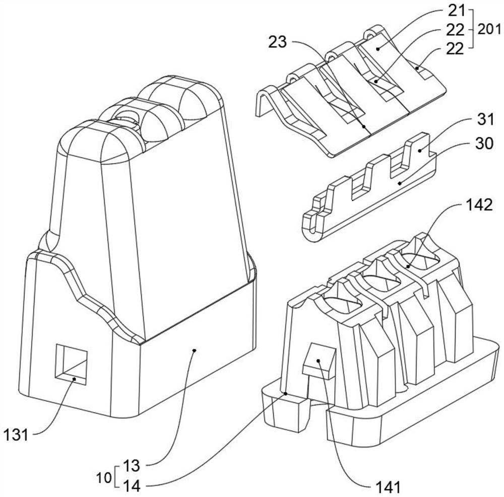
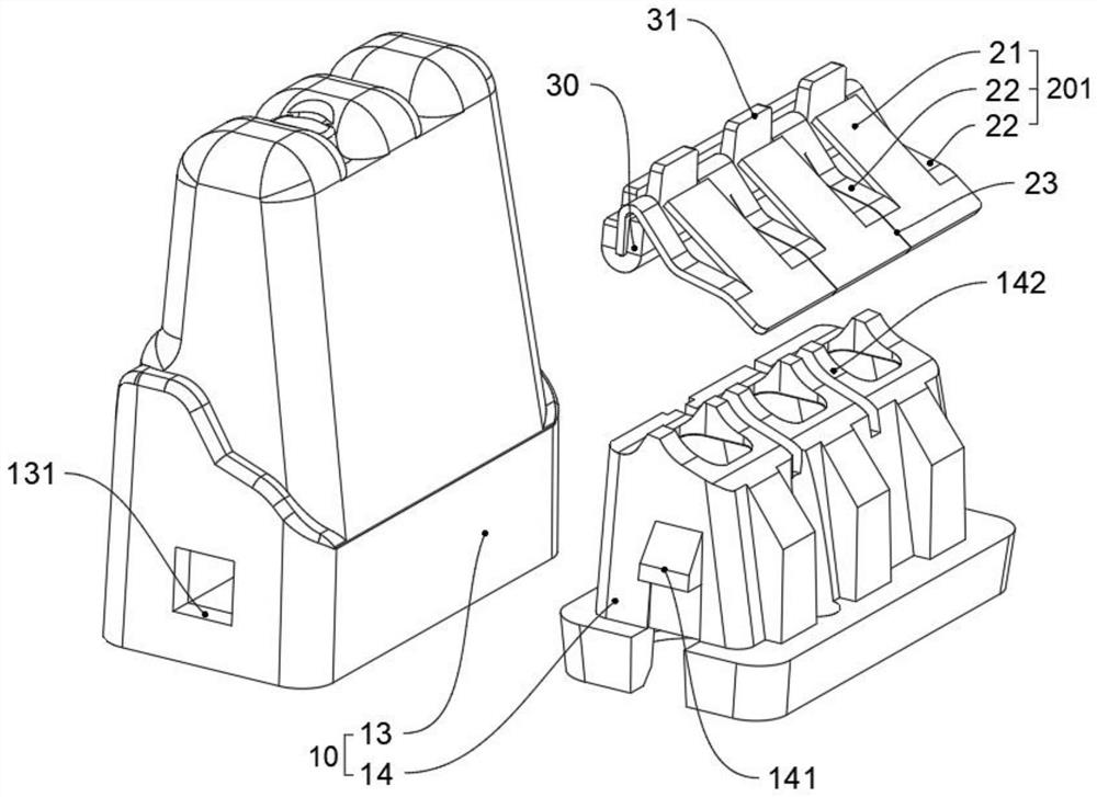
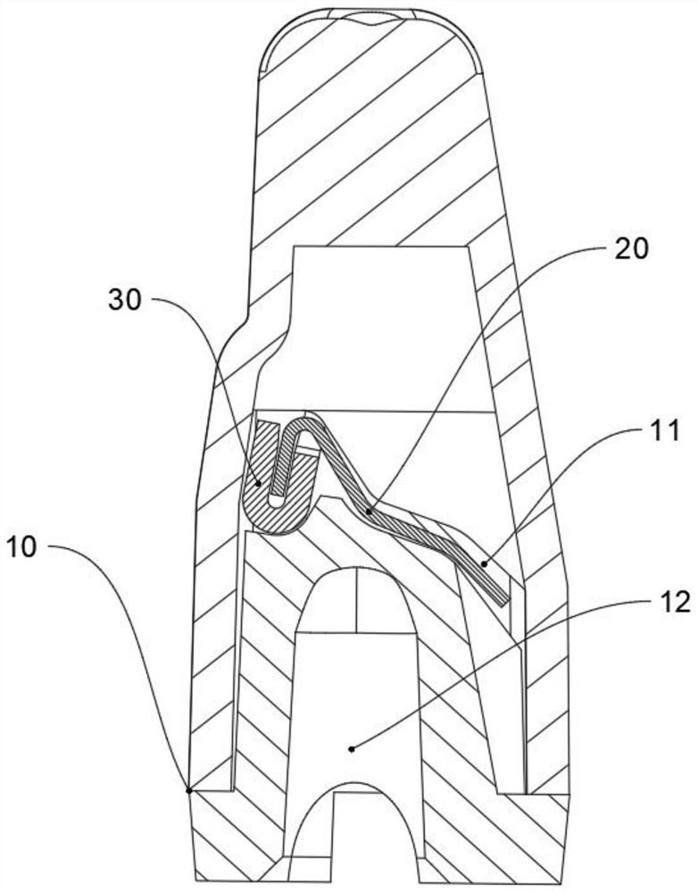
[0071] see Figure 1 to Figure 5 , set the wire crimping units 201 on the elastic sheet 20 into a plurality, and set the plurality of wire crimping units 201 as a horizontal connection structure. The design, taking three wire insertion holes 12 as an example, can satisfy a wire connector with an odd number of wire insertion holes 12. Specifically, a plurality of wire pressing units 201 are arranged in a row, and two adjacent wire pressing units 201 are deformed by one of them. In addition, the elastic sheet 20 is arranged to leave a first assembly gap 24 between the planes after the third bending angle 223 of each deformation portion 22 is bent, and the conductive sheet 30 is along the The middle part is bent so that a second assembly gap 34 is left between the bent planes of the conductive sheet 30; the conductive sheet 30 is inserted into the first assembly gap 24 through the end corresponding to the toothed structure 31, and the teeth on the The number of teeth corresponds...

Embodiment 2

[0073] see Figure 6 to Figure 10 , the wire pressing units 201 on the elastic sheet 20 are arranged in multiples, and the plurality of wire pressing units 201 are arranged in a double-row arrangement structure, and the two rows of wire pressing units 201 are arranged in a vertical connection structure. The unit 201 is set as a horizontal connection structure, and the third bending angle 223 of the deformation part 22 is bent to form a vertical connection surface, and the two vertically adjacent pressing line units 201 are combined through the vertical connection surface, so that the adjacent two A third assembly gap 25 is left between the bent planes of the third bending corners 223 of the deformed portions 22 of each of the crimping units 201 ; An arc protruding portion extends toward the side of the pressing portion 21, and each arc protruding portion is bent inward to form the supporting surface 26 of the bent inner corner of the conductive sheet 30; the conductive sheet 3...


PUM


Abstract

The invention relates to the technical field of conductive connection, in particular to a self-coupling wire connector adopting a bending compression and conducting strip bending mode, which comprises a main body, an elastic sheet and a conducting strip, a coupling space for accommodating the elastic sheet and the conducting strip is arranged in the main body, and a wire insertion hole penetrating through the coupling space is formed in the main body; the elastic sheet and the conductive sheet are assembled in the coupling space, and the elastic sheet and the conductive sheet are kept in a self-coupling state through the coupling space; when the wire connector is used, the wire abuts against the elastic piece and the conducting strip, the elastic piece and the conducting strip are forced to be self-coupled, the flexible matching degree of the elastic piece and the conducting strip is improved, the wire can be more reasonably inserted into the wire connector, it can be guaranteed that the wire is firmly connected with the wire connector, and it can also be guaranteed that the conducting strip and the wire achieve the better conducting effect; and through the design, the riveting or welding procedure is removed, and the cost and time consumption in the production and manufacturing process are reduced.

Description

technical field [0001] The invention relates to the technical field of conductive connection, in particular to a self-coupling wire connector adopting the method of bending and pressing and bending conductive sheets. Background technique [0002] Existing plug-in connectors are divided into shell restraint structure connectors and hardware restraint structure connectors. [0003] The plug-in connector of the housing restraint structure is composed of a V-shaped shrapnel and a conductive piece that is not connected to the shrapnel. The V-shaped shrapnel and the conductive piece are bound in a specific structure at different positions constrained by its main body. When the wire is not inserted Before, the shrapnel and the conductive sheet are in a non-connected state. When the wire is inserted, one end of the V-shaped shrapnel deforms and presses the wire on the conductive sheet. At this time, due to the simple structure of the shrapnel, the effective decomposition of the comp...

Claims


Application Information

Patent Timeline
IPC IPC(8): H01R13/40H01R13/02H01R13/639
CPCH01R13/40H01R13/02H01R13/639H01R11/09H01R4/48185
Inventor 谭强
Owner DONGGUAN CHENMING ELECTRONICS TECH
Learn More