A kind of heavy metal waste liquid treatment equipment for industrial production
What is Al technical title?
Al technical title is built by PatSnap Al team. It summarizes the technical point description of the patent document.
A technology for waste liquid treatment and heavy metals, which is applied in filtration treatment, water/sewage multi-stage treatment, water/sludge/sewage treatment, etc. It can solve problems such as excessive drug delivery, improve cleaning efficiency, avoid clogging, reduce The effect of operational difficulty
Active Publication Date: 2021-08-03
江苏卓纳环保科技有限公司
View PDF0 Cites 0 Cited by
Summary
Abstract
Description
Claims
Application Information
AI Technical Summary
This helps you quickly interpret patents by identifying the three key elements:
Problems solved by technology
Method used
Benefits of technology
Problems solved by technology
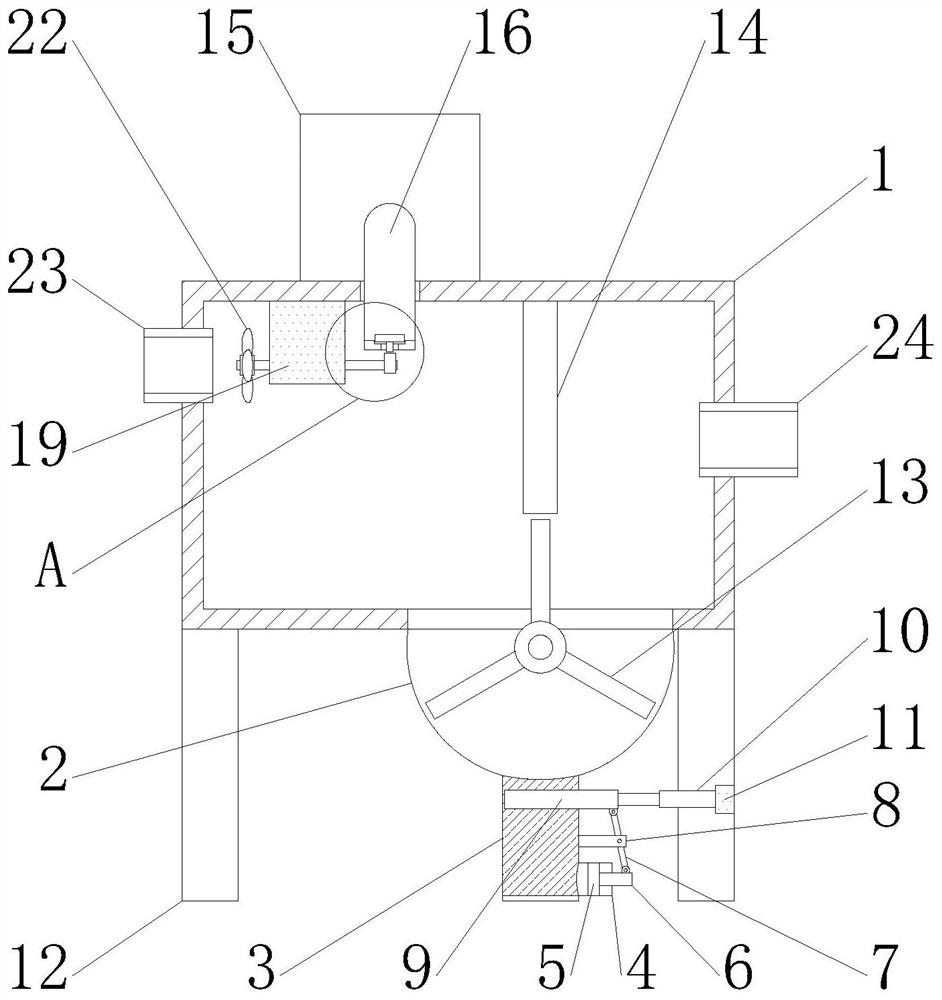
[0006] The object of the present invention is to provide a heavy metal waste liquid treatment equipment for industrial production in order to solve the above problems. The heavy metal waste liquid treatment system for industrial production is simple in structure and easy to operate. , which is conducive to the precipitation reaction of heavy metals in wastewater, and the speed of cam rotation is beneficial to control the dosage of chemicals, which reduces the difficulty of operation, facilitates control, and is conducive to the proper dosage of chemicals, avoiding the reduction of wastewater treatment effect and To solve the problem of excessive drug delivery, the heavy metal waste liquid treatment system used in industrial production filters the sediment through the filter screen, and the filter plate can be easily replaced through the rotation of the filter plate to avoid blockage of the filter plate, and through the vertical pipe. discharge, which improves the convenience of operation, improves the cleaning efficiency, and facilitates the timely removal of sediment
Method used
Image
Click on the blue label to locate the original text in one second.
Reading with bidirectional positioning of images and text.
Examples
Embodiment Construction
[0022] The following will clearly and completely describe the technical solutions in the embodiments of the present invention with reference to the accompanying drawings in the embodiments of the present invention. Obviously, the described embodiments are only some, not all, embodiments of the present invention. Based on the embodiments of the present invention, all other embodiments obtained by persons of ordinary skill in the art without making creative efforts belong to the protection scope of the present invention.
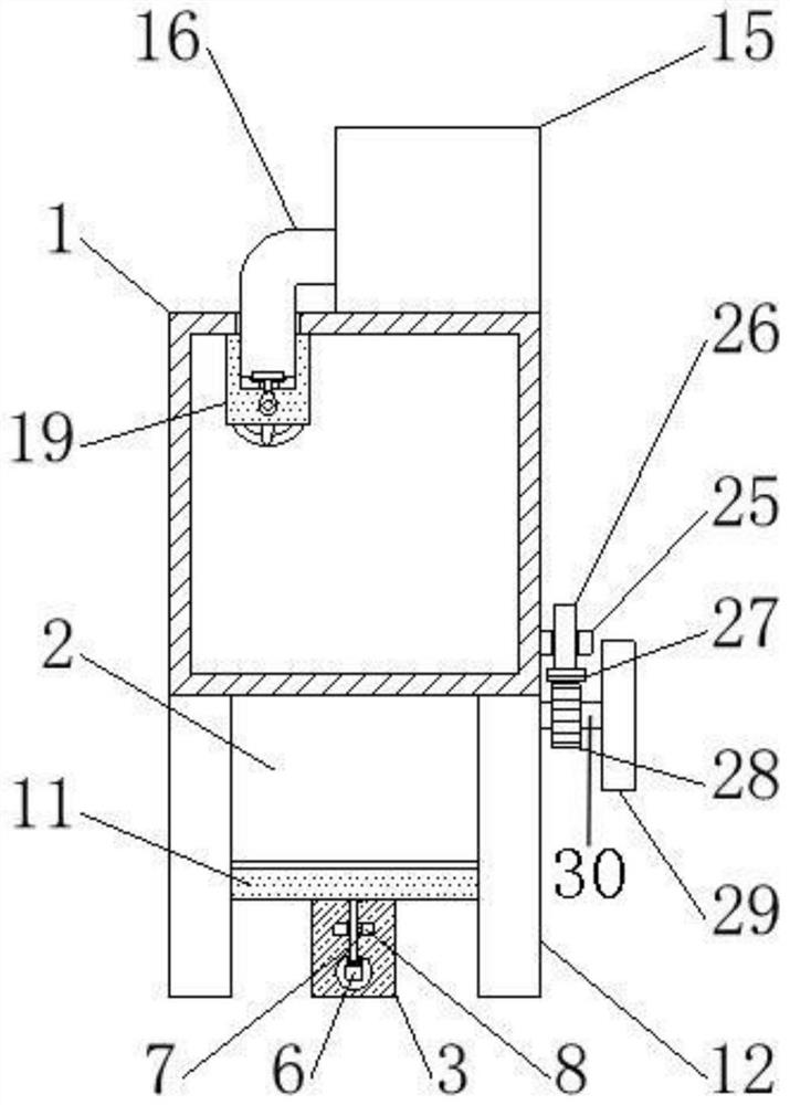
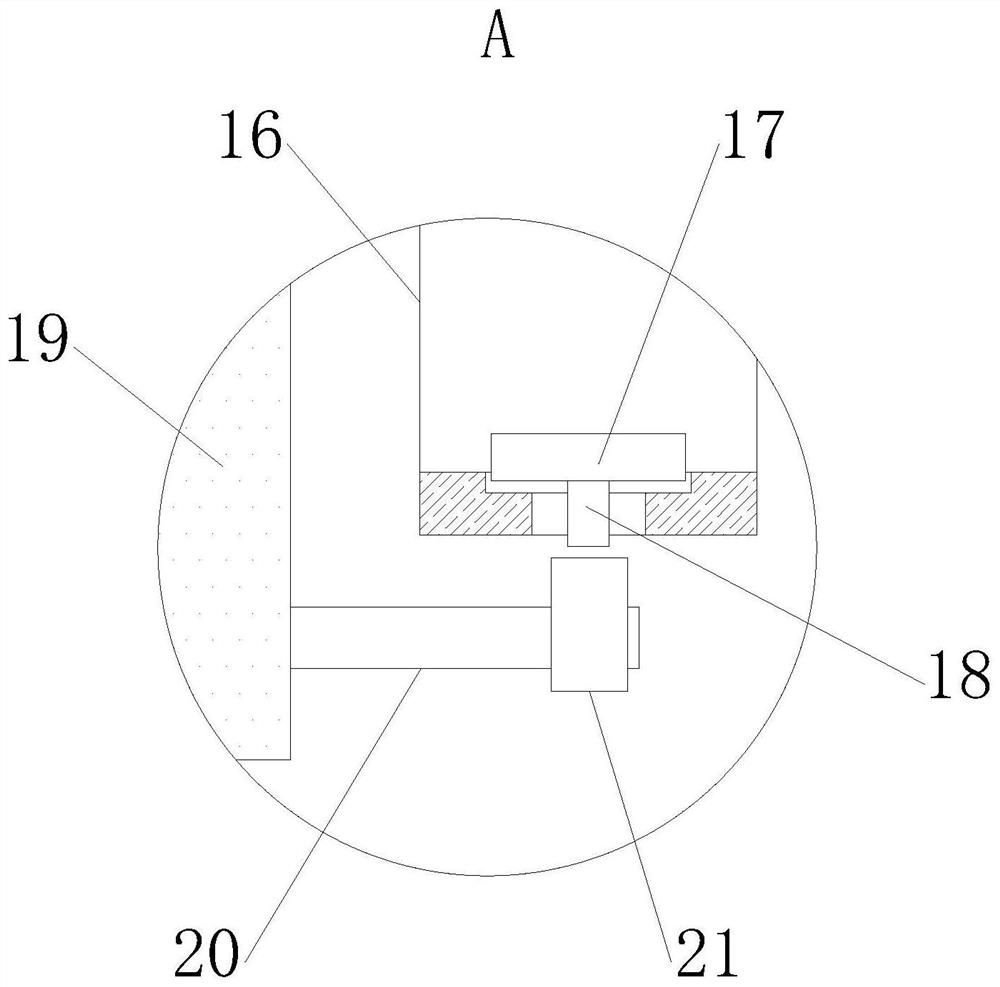
[0023] see Figure 1-3 As shown, a heavy metal waste liquid treatment equipment for industrial production includes a housing 2 installed at the bottom of the box body 1, a filter mechanism for filtering the heavy metal waste liquid, and a filter mechanism for introducing chemicals into the box body 1 The internal flow guide mechanism, wherein the two sides of the top of the box body 1 are respectively communicated with the water inlet pipe 23 and the water out...
PUM
Abstract
The invention belongs to the field of waste liquid treatment, in particular to a heavy metal waste liquid treatment equipment for industrial production, including a box body, a shell, a vertical pipe, a connecting pipe, a piston, a connecting rod, a rotating rod, a bearing, a baffle, Electric push rod, cross bar, support leg, filter plate, partition, liquid storage tank, diversion tube, sealing plug, fixed rod, fixed plate, rotating shaft, cam, impeller, water inlet pipe, water outlet pipe, fixed block, bolt, Blocks, gears, handles and fixed shafts. The heavy metal waste liquid treatment system for industrial production discharges waste water and chemicals into the box, which is conducive to the precipitation reaction of heavy metals in the waste water, and the speed of the cam rotation is conducive to controlling the dosage of chemicals and avoiding waste water treatment. The problem of reduced effect and excessive drug delivery; the sediment is filtered through the filter and discharged through the vertical pipe, which improves the convenience of operation, improves the cleaning efficiency, and facilitates the timely removal of sediment.
Description
technical field [0001] The invention belongs to the field of waste liquid treatment, in particular to a heavy metal waste liquid treatment equipment for industrial production. Background technique [0002] Water resources play an important role in the development of the national economy and social production, and are also an indispensable part of people's lives. However, with the rapid development of industry and agriculture, a large amount of industrial wastewater is discharged, which makes the pollution of heavy metals in water increasingly serious. According to statistics, China About 40 billion tons of industrial wastewater is produced every year, of which heavy metal wastewater accounts for about 60%. These wastewater seriously pollute surface water and groundwater, resulting in a sharp decline in the total amount of available water resources. Heavy metal wastewater generally comes from mining, metal smelting and processing, In industries such as electroplating, tanning...
Claims
Application Information
Patent Timeline
Application Date:The date an application was filed.
Publication Date:The date a patent or application was officially published.
First Publication Date:The earliest publication date of a patent with the same application number.
Issue Date:Publication date of the patent grant document.
PCT Entry Date:The Entry date of PCT National Phase.
Estimated Expiry Date:The statutory expiry date of a patent right according to the Patent Law, and it is the longest term of protection that the patent right can achieve without the termination of the patent right due to other reasons(Term extension factor has been taken into account ).
Invalid Date:Actual expiry date is based on effective date or publication date of legal transaction data of invalid patent.